Sign In
Upload
Download
Table of Contents
Contents
Add to my manuals
Delete from my manuals
Share
URL of this page:
HTML Link:
Bookmark this page
Add
Manual will be automatically added to "My Manuals"
Print this page
×
Bookmark added
×
Added to my manuals
Manuals
Brands
Limitorque Manuals
Controller
SB Series
Installation and maintenance manual
Limitorque SB Series Installation And Maintenance Manual
Hide thumbs
1
2
Table Of Contents
3
4
5
6
7
8
9
10
11
12
13
14
15
16
17
18
19
20
21
22
23
24
25
26
27
28
29
30
31
32
33
34
35
36
37
38
39
40
41
42
43
44
45
46
47
48
49
50
51
52
53
54
55
56
57
58
59
60
61
62
63
64
65
66
67
68
69
70
71
72
73
74
75
76
77
78
79
80
81
82
83
84
85
86
87
88
89
90
91
92
93
94
95
96
page
of
96
Go
/
96
Contents
Table of Contents
Troubleshooting
Bookmarks
Table of Contents
Table of Contents
1 Introduction
Purpose
User Safety
2 Product Capabilities and Features
Initial Inspection and Storage Instructions
Product Identification
Inspection and Recording
Storage Procedure
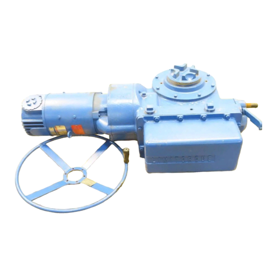
Figure 2.1 - Typical SMB
3 Actuator Weights
Table 3.1 - Actuator Weights
4 Installation Instructions
Safety Precautions
Safety Practices
Prepare Initial Actuator
Mounting Base
Stem Acceptance
Table 4.1 - Mounting Base Dimensions
Table 4.2 - Maximum Stem Acceptance
Setting Limit Switch
Two-Train Geared Limit Switch
Figure 4.1 - Two-Train Geared Limit Switch-Rotor-Type
Table 4.3 - Two-Train Geared Limit Switch-Parts List
Four-Train Geared Limit Switch
Figure 4.2 - Four-Train Geared Limit Switch-Rotor-Type
Table 4.4 - Four-Train Geared Limit Switch-Parts List
Setting Torque Switch
SMB-000 Double Torque Switch
Figure 4.3 - SMB-000 Double Torque Switch
Table 4.5 - SMB-000 Double Torque Switch Parts List
Figure 4.4 - SMB-00 Double Torque Switch
Table 4.7 - SMB-0 through SMB-5 Double Torque Switch Parts List
Position Indication
Local Position Indicator
Remote Position Indicator (50 Ohm or 1000 Ohm Potentiometer)
Remote Position Indicator (Resistance-To-Current Signal Converter)
Figure 4.6 - Typical Connection for a 50-Ohm Potentiometer
Additional Electrical Components
Reversing Starter
Overload Relays
Figure 4.9 - Typical Connection for PT20SD R/I Converter
Control Station
Figure 4.10 - Typical Wiring Diagram-Built-In Reversing Starter and Control Station for a Three-Phase Power Supply
5 Operation
Motor Operation
Manual Operation
6 Maintenance
Routine Maintenance
Major Maintenance
Lubrication
Lubrication Inspection
Standard Lubricants
Minimum Lubricant Qualities Required
7 SMB Disassembly & Reassembly
Smb-000
SMB-000 Disassembly
SMB-000 Reassembly
To Replace Stem Nut Only
Gasket Instructions
Figure 7.1 - SMB-000 Parts Diagram- Side View
Figure 7.2 - SMB-000 Parts Diagram - Top View
Figure 7.3 - SMB-000 Exploded View
Table 7.1 - SMB-000 Parts List
Smb-00
SMB-00 Disassembly
SMB-00 Reassembly
To Replace Stem Nut Only
Gasket Instructions
Figure 7.4 - SMB-00 Parts Diagram - Motor End View
Figure 7.5 - SMB-00 Parts Diagram - Top View
Figure 7.6 - SMB-00 Parts Diagram - Side View
Figure 7.7 - SMB-00 Parts Diagram - Side Mounted Handwheel Detail
Figure 7.8 - SMB-00 Exploded View
Table 7.2 - SMB-00 Parts List
SMB-0, 1, 2, 3, 4, 4T Disassembly
SMB-0, 1, 2, 3, 4, 4T Reassembly
To Replace Stem Nut Only
Gasket Instructions
Figure 7.9 - SMB-0 through SMB-4 and 4T Parts Diagram - Top View
Figure 7.10 - SMB-0 through SMB-4 and 4T Parts Diagram - Worm Shaft Side View
Figure 7.11 - SMB-0 through SMB-4 and 4T Parts Diagram - Drive Sleeve Side View
Figure 7.12 - SMB-0 through SMB-4 and 4T Exploded View
Table 7.3 - SMB-0 through SMB-4 and 4T Parts List
SMB-5 and SMB-5T Reassembly
Figure 7.13 - SMB-5 and 5T Parts Diagram
Figure 7.14 - SMB-5 and 5T - Top View
Figure 7.15 - SMB-5 and 5T Declutch Housing Detail
Figure 7.16 - SMB-5 and 5T Exploded View
Table 7.4 - SMB-5 and 5T Parts List
8 SB Disassembly and Reassembly
Sb-00
Disassembly/Stem Nut Removal
Reassembly/Stem Nut Installation 8.2
Figure 8.1 - SB-00 Parts Diagram
Table 8.1 - SB-00 Parts List
Disassembly/Stem Nut Removal
Reassembly/Stem Nut Installation 8.3
Figure 8.2 - SB-0 Parts Diagram
Table 8.2 - SB-0 Parts List
Disassembly/Stem Nut Removal
Reassembly/Stem Nut Installation 8.4
Figure 8.3 - SB-1 Parts Diagram
Table 8.3 - SB-1 Parts List
Disassembly/Stem Nut Removal
Reassembly/Stem Nut Installation 8.5
Figure 8.4 - SB-2 Parts Diagram
Table 8.4 - SB-2 Parts List
Disassembly/Stem Nut Removal
Reassembly/Stem Nut Installation 8.6
Figure 8.5 - SB-3 Parts Diagram
Table 8.5 - SB-3 Parts List
Disassembly/Stem Nut Removal
Reassembly/Stem Nut Installation
Figure 8.6 - SB-4 Parts Diagram
Table 8.6 - SB-4 Parts List
9 Troubleshooting
10 How to Order Parts
Table 10.1 - Space Heater Size Per Voltage Rating
11 Regulatory Information
Advertisement
Quick Links
1
Setting Limit Switch
Download this manual
140-11000
Limitorque Actuation Systems
July 2003
Limitorque
®
SMB Series/SB Series
Installation and Maintenance
Table of
Contents
Previous
Page
Next
Page
1
2
3
4
5
Advertisement
Table of Contents
Need help?
Do you have a question about the SB Series and is the answer not in the manual?
Ask a question
Questions and answers
Related Manuals for Limitorque SB Series
Controller Limitorque SMB Series Installation And Maintenance Manual
(96 pages)
Controller Limitorque WTR Series Installation & Maintenance
(36 pages)
Controller Limitorque L120 Series Installation & Maintenance
(35 pages)
Table of Contents
Save PDF
Print
Rename the bookmark
Delete bookmark?
Delete from my manuals?
Login
Sign In
OR
Sign in with Facebook
Sign in with Google
Upload manual
Upload from disk
Upload from URL


Need help?
Do you have a question about the SB Series and is the answer not in the manual?
Questions and answers