
Related Manuals for Lukas HTS 99

Summary of Contents for Lukas HTS 99
- Page 1 Operating instructions for rescue equipment Door opener HT 90 HT 99 JL-8 84150612985 EN Edition 11.2019 replaces 01.2008 (Translation of original operating instructions)
-
Page 2: Table Of Contents
4.4 Control of the operating movements 4.5 Hydraulic supply 4.6 Hoses 5. Connecting the equipment 5.1 General information 5.2 Coupling of screwed couplings (on HT 90) 5.3 Coupling of Flat-Face quick-disconnect couplings (on HT 99 and JL-8) 6. Operation 6.1 Preparatory measures 6.2 Danger information 6.3 Starting points... - Page 3 Content Page 9. Repairs 9.1 General information 9.2 Preventative service 9.3 Repairs 10. Troubleshooting 11. Technical data 11.1 Recommended hydraulic fluids 11.2 Operating and storage temperature ranges 12. EC Declaration of Conformity 13. Notes...
-
Page 4: Danger Classifications
1. Danger classifications We differentiate between various different categories of safety instructions. The table shown below provides an overview of the assignment of symbols (pictograms) and signal words to the specific danger and the possible consequences. Damage / Pictogram Key word Definition Consequences injury to Death or severe DANGER! Immediate danger injury Potentially Potential death or WARNING! dangerous serious injury situation Less dangerous Minor or slight CAUTION! situation injury Damage to the equipment, Risk of damage damage to the ATTENTION! to property/ environment, environment damage to surroundings Handling tips and No injury/damage other important/... -
Page 5: Product Safety
2. Product safety LUKAS products are developed and manufactured to ensure the best performance and quality when used as intended. The safety of the operator is the most important consideration in product design. Furthermore, the operating instructions are intended to help in using LUKAS products safely. In addition to the operating instructions, all generally applicable, statutory and other binding rules for accident prevention and for environmental protection must be complied with and instructed. The equipment must only be operated by persons with appropriate training in the safety aspects of such equipment – otherwise, there is a danger of injury. We would like to point out to all users that they should read carefully the operating instructions and the instructions contained therein before they use the equipment, and that they should be carefully followed. We also recommend that you have a qualified trainer show you how to use the product. - Page 6 In the event of malfunctions, Do not carry out any changes immediately deactivate the (additions or conversions) equipment and secure it. to the equipment without Repair the fault immediately. obtaining the approval of LUKAS beforehand. Observe all safety and danger All safety and danger information on the device and information on the device must in the operating instructions. always be complete and in a legible condition. Any mode of operation which Observe all intervals for compromises the safety and/ recurring tests and/or or stability of the device is inspections that are prescribed forbidden! or stated in the operating instructions. Safety devices must never be The maximum permitted disabled! operating pressure noted on the equipment must not be exceeded. Make sure before switching Only genuine LUKAS on/starting up the device and accessories and spare parts during its operation that this are to be used for repairs. will put no one in danger. Please ensure that, when working with this equipment or during transportation of such, you don’t get caught up in the...
- Page 7 The equipment is filled with When working with or storing hydraulic fluid. This hydraulic the equipment, ensure that the fluid can be detrimental to function and the safety of the equipment are not impaired health if it is swallowed or its vapour is inhaled. Direct by the effects of severe contact with the skin must be external temperatures or that avoided for the same reason. the equipment is damaged in Also, when handling hydraulic any way. Please note that the fluid, note that it can negatively equipment can also heat up affect biological systems. over a long period of use. Make sure there is adequate Before transporting the lighting while working. equipment, always ensure that the accessories are positioned in such a way that they cannot cause an accident. Always keep these operating Dispose properly of all instructions easily accessible disassembled parts, oil and at the place of operation. left-over fluid, as well as packaging materials! The generally applicable, legal and other binding national and international regulations pertaining to the prevention of accidents and protection of the environment apply and are to be implemented in addition to the operating instructions.
-
Page 8: Appropriate Use
LUKAS rescue equipment may only be used in areas at risk of explosion if an explosion has been prevented by appropriate measures. You must also take into account the fact that sparks may be created, for example by spreading or squashing an object. -
Page 9: Functional Description
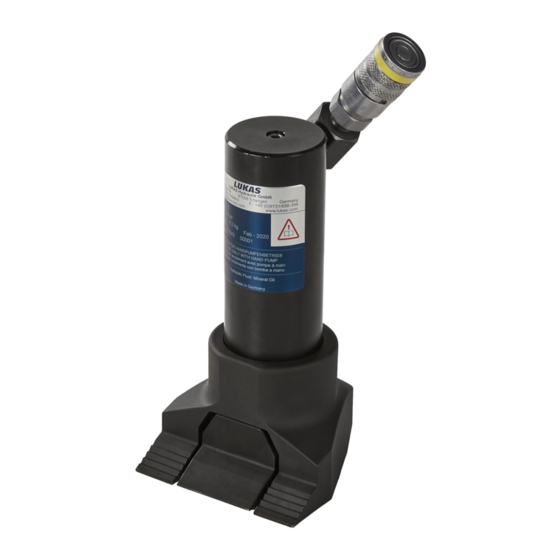
4. Functional description 4.1 Description The door openers are single-acting hydraulic cylinders. Extension is hydraulic, retraction is mechanical by a spring return. 4.2 Unit in detail HT 90 1 Female coupling 2 Cylinder 3 Claw 4 Base 1 Female coupling 2 Cylinder 3 Claw 4 Base... -
Page 10: Wiring Diagram
JL-8 1 Female coupling 2 Cylinder 3 Claw 4 Base 4.3 Wiring diagram The wiring diagram is shown here in simplified form to enable comprehension of the function. 4.4 Control of the operating movements Pressure is applied by a hand pump. Due to the spring force, the piston rod retracts again as soon as pressure stops being applied and the pressure can be released via the supply line (not blocked and no pressure applied). -
Page 11: Hydraulic Supply
4.5 Hydraulic supply Only LUKAS hand pumps may be used to drive the equipment. If the hand pump is a different make, you must make sure that it complies with LUKAS specifications, otherwise potential dangers may occur, for which LUKAS cannot be held responsible. Ensure in particular that the authorised operating pressure for LUKAS equipment is not exceeded. -
Page 12: Coupling Of Screwed Couplings (On Ht 90)
5.1.3. Jack Rabbit Tool JL-8 A hose with a (Flat-Face) female quick-disconnect coupling is mounted on the device. It is coupled directly to the hand pump. 5.2 Coupling of screwed couplings (on HT 90) The device is connected to the hydraulic pump without the risk of connection error by means of screwed coupling halves (female and male counterparts). Remove the dust caps before coupling and then push the male connector into the female connector. Then screw the threaded sleeve of the female connector on to the male thread on the male coupling and tighten hand-tight. The connection is now made. Uncoupling is done in the reverse order. NOTE: Coupling of the devices is only possible when the hoses are depressurised. For dust protection, the supplied dust caps must be refitted. 5.3 Coupling of Flat-Face quick-disconnect couplings (on HT 99 and JL-8) The device is connected to the hand pump without the risk of connection error using Flat-Face quick-disconnect coupling halves (female and male). -
Page 13: Operation
6. Operation 6.1 Preparatory measures 6.1.1 Inspection of the hand pump See separate operating instructions for the corresponding hand pump. 6.2 Danger information Before operating the door opener, you should ensure that no participants or persons not involved are put at risk from the movement of the piston rod or from flying fragments. Also avoid unnecessary damage to property belonging to others, objects not involved by the cylinder pistons or flying fragments. -
Page 14: Procedure
6.4 Procedure When attaching the device, it must be pressed firmly and as deeply as possible into the door gap with the claws or driven through the anvil (see picture). Anvil When working in potentially explosive environments, sparking must be avoided. WARNING / CAUTION / ATTENTION! - If the device slips off metal or stone, there is a risk of sparks. - The door opener must be held firmly to prevent injury by falling down when the door is forced open. - There is a risk of injury in the area of doors that spring open or are forced open. 6.5 Retraction of the piston When retracting the piston, make sure that the base (item 4) is lowered between the claw (item 3). Turn the base if necessary. WARNING / CAUTION! When retracting the piston, there is a risk of crushing between the claw and the base. -
Page 15: Dismantling The Equipment / Deactivation Following Operation
7. Dismantling the equipment / deactivation following operation 7.1 Door opener At the end of the work, the door openers must be retracted until they reach the end position. This relieves hydraulic and mechanical stress on the device. NOTE: When door openers are in storage, fluctuations in ambient temperature can cause the pistons to move slightly. This physical phenomenon is due to the differing expansion of the enclosed hydraulic fluid. 7.2 Hand pump After completing the work, the hand pump must be depressurised. -
Page 16: Maintenance And Service
8. Maintenance and service The devices are subject to very high mechanical stress. Therefore, a visual inspection must be carried out after every use and at least once a year. These inspections enable the early detection of wear and tear, which means that punctual replacement of this wearing parts prevents breakages from occurring. Every 3 years or when there might be doubts regarding the safety or reliability of the unit, an additional function check is to be carried out (in this connection, comply with the applicable national and international regulations with regard to the maintenance intervals of rescue equipment). ATTENTION! Clean off any dirt before checking the device! WARNING / CAUTION / ATTENTION! To perform maintenance and repairs, personal protection equipment appropriate for the work is an absolute requirement. Inspections to be carried out: Visual inspection Door opener • Cylinder and piston rod undamaged and not deformed, • Correct and firm fit of claw and base,... -
Page 17: Repairs
You should always contact LUKAS or an authorised dealer before using couplings from another manufacturer. ATTENTION! Because LUKAS rescue equipments are appropriate for highest achievements, only components may be exchanged, which are specified in the spare parts list of the appropriate equipment. Other components in the device may only be replaced if: - You have participated in an appropriate LUKAS service training course. - You have the explicit permission of LUKAS Customer Service (on request, verification that permission may be granted. To be checked in each individual case!) A functional test must be carried out after repairs: Extend the device 2-3 times in the unloaded state so that any air present can escape from the system. 9.2 Preventative service 9.2.1 Care instructions The exterior of the equipment is to be cleaned from time to time in order to protect it from external corrosion. Oil is to be applied to the metallic surfaces. -
Page 18: Repairs
9.2.3 Replacing the hydraulic fluid - The hydraulic fluid must be replaced after approx. 200 deployments, but after three years at the latest, - It must always be changed whenever the hydraulic fluid for the accompanying hand pump is changed. This is to prevent the fresh hydraulic fluid from becoming contaminated by the used fluid from the rescue equipment. ATTENTION! Always replace the hydraulic fluid over a liquid collection container and dispose of the collected fluid in a proper manner. ATTENTION! The hydraulic fluid must be completely replaced if the application conditions (ambient temperatures) change substantially. When selecting a suitable hydraulic fluid, please refer to the chapter “Recommended hydraulic fluids”. Procedure: 1. Retract the door opener fully and depressurise the hydraulic system. 2. Remove the coupling on the door opener. 3. Drain off the hydraulic fluid. 4. Flush 5. Reassemble the coupling. 6. Connect hand pump with fresh hydraulic fluid. - Page 19 9.3.2 Flat Face quick-disconnect couplings (on JL-8) The quick-disconnect couplings must be replaced if: - there is external damage, - the lock does not work, - hydraulic fluid continues to leak in the coupled and/or uncoupled state. WARNING / CAUTION / ATTENTION! Never repair couplings: they must be replaced by genuine LUKAS parts! Procedure: 1. Remove the coupling from the hose line. 2. Mount the new coupling on the hose line and tighten with a torque of M = 40 Nm (use Teflon tape). 9.3.3 Screwed couplings (on HT90) The screwed couplings must be replaced if: - there is external damage, - the lock does not work, - hydraulic fluid continues to leak in the coupled and/or uncoupled state. WARNING / CAUTION / ATTENTION!
-
Page 20: Troubleshooting
9.3.5 Decals All damaged and/or illegible labels (safety notices, type plate, etc.) must be replaced. Procedure: 1. Remove damaged and/or illegible decals. 2. Clean surfaces with acetone or industrial alcohol. 3. Affix new decals. Take care to affix the labels in the correct positions. If this is no longer known, you should ask your authorised LUKAS dealer or contact LUKAS directly. 10. Troubleshooting Fault Check Cause Solution Cylinder does not Check the hydrau- Insufficient hydrau- Refill the hydraulic extend, lic fluid level in the lic fluid in the hand fluid. extends too slow- pump supplying the pump. ly or stops when fluid. extending Check that the Pressure relief valve Close the pressure pressure relief valve on hand pump open. relief valve on the on the hand pump is hand pump. - Page 21 Cause Solution Cylinder ex- Check that all Leaky connection. Tighten loose con- tends, but does connections are fully nection. not maintain the tightened. pressure Check the cylinder Leaking seals. Have the leaks for leaks. repaired by an authorised dealer, by personnel specially trained by LUKAS, or by LUKAS itself. Internal leakage of the Have the hand hand pump. pump serviced by an authorised dealer, by personnel specially trained by LUKAS or by LUKAS directly. Cylinder does Check that the Pressure relief valve Fully open the pres- not retract, only pressure relief valve on hand pump partly sure relief valve on partially retracts on the hand pump is closed.
- Page 22 Coupling defective Coupling must be replaced immediately Hydraulic fluid Are the hoses defec- Leak, possible dam- Replace hose line. leak on the hose tive? line or its inserts Damage on the Check hose line for Mechanical damage Replace hose line. surface of the external damage. or contact with ag- hose line gressive agents Leak on the cou- Is the coupling dam- Coupling defective Coupling must be plings aged? replaced immediately Contact an authorised LUKAS dealer or the LUKAS Customer Service Department directly if the malfunctions cannot be rectified! The address for the LUKAS Customer Service department is: LUKAS Hydraulik GmbH Weinstrasse 39, D-91058 Erlangen, Germany PO Box 2560 D-91013 Erlangen Tel.: (+49) 09131 / 698 - 348 Fax.: (+49) 09131 / 698 - 353...
-
Page 23: Technical Data
11. Technical data Because all values are subject to tolerances, there may be minor differences between the data for your device and the data in the following tables. Device type HT 90 HT 99 JL-8 Item number 81-85-21 81-85-31 362R549 Compression [kN] force (in all [lbf.] 21358 21358 7869 operating ranges) [mm] Piston stroke [in.] 3.94 3.94 7.48 [mm] Length (retracted) [in.] 8.11 8.11 13.2 [mm] Length (extended) [in.]... -
Page 24: Recommended Hydraulic Fluids
11.1 Recommended hydraulic fluids 11.1.1 Recommended hydraulic fluids for HT 90 and HT 99 Mineral oil DIN ISO 6743-4 for LUKAS hydraulic equipment and others Oil temperature range Oil code Viscosity rating Remarks -20 ..+55°C HM 10 VG 10 Oil temperature range Oil code Viscosity rating Remarks -4.0 ..+131°F HM 10 VG 10 Recommended range of viscosity: 10...200 mm²/s (10…200 cSt.) Supplied with HM 10 DIN ISO 6743-4. ATTENTION! Before using hydraulic fluids which do not correspond to the above-mentioned specifications and/or are not purchased from LUKAS, you must contact LUKAS itself. -
Page 25: Ec Declaration Of Conformity
12. EC Declaration of Conformity... -
Page 27: Notes
13. Notes... - Page 28 A unit of IDEX Corporation Weinstrasse 39, D-91058 Erlangen, Germany Tel.: (+49) 0 91 31 / 698 - 0 Fax.: (+49) 0 91 31 / 698 - 394 e-mail: lukas.info@idexcorp.com www.lukas.com Made in GERMANY door opener_manual_84150612985_en.indd © Copyright 2019 LUKAS Hydraulik GmbH...
Need help?
Do you have a question about the HTS 99 and is the answer not in the manual?
Questions and answers