Table of Contents
Advertisement
Advertisement
Table of Contents

Related Manuals for LORCH V40


Summarization of Contents
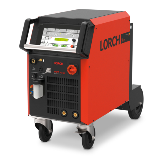
Machine Overview
Machine Elements Identification
Lists and labels the main external components of the welding machine.
Safety Precautions
Operational Safety Requirements
Outlines the general safety requirements for operating and maintaining welding machines.
Relevant Standards for Testing
Specifies the relevant standard (IEC 60974-4) for in-service inspection and testing.
Common Logic Functions
Component Functionality
Details the functions and causes for components like fans and pumps.
Pump Operation Test
Describes the procedure for testing the cooling pump.
Parameter Reset Procedures
Explains how to reset machine parameters to factory defaults.
Master Reset Functionality
Details the process for a full master reset, including a caution.
Inverter Principle
Welding Inverter Structure
Explains the fundamental components and operation of a welding inverter.
DK-MAPRO Control Board
Board Functions and Responsibilities
Lists the responsibilities of the DK-MAPRO pc-board in welding process control.
LED Indicators Status
Describes the states and meanings of LEDs for normal and malfunction conditions.
DIP Switch and Fuse Configuration
Details DIP switch settings and an overview of fuses on the board.
Measuring Points and Connectors
Lists test points and connectors on the DK-MAPRO board.
DK-DCI40 / DK-ACI40 Front Panel Board
Front Panel Board Functions
Outlines the role of the DK-DCI40/DK-ACI40 pc-board in machine operation.
Front Panel Layout
Shows the layout of buttons and LEDs on the front panel pc-board.
DK-DCI45 / DK-ACI45 Front Panel Board
V Mobile Front Panel Functions
Describes the DK-DCI45/DK-ACI45 pc-board's function for V mobile machines.
V Mobile Front Panel Layout
Displays the component layout for the front panel pc-board.
Front Panel Function Test
Explains how to perform an internal function test of the front panel components.
DK-DCDRV Primary Driver Board
Primary Driver Board Functions
Details the DK-DCDRV pc-board's role in managing the power unit's primary drive level.
Power Unit Encoding
Explains how the power unit type is set using DIP switches.
LED Status Indicators
Describes the LED indicators for normal operation and malfunctions.
Voltage and Temperature Measuring Points
Lists test points and their results for voltage and temperature sensors.
Board Connectors and Schematic
Lists connectors and provides the circuit diagram for the primary driver.
DK-DCDRV MOSFET and Board Changes
MOSFET and PC-Board Revision History
Details changes in MOSFET types and pc-board versions over time.
Identifying New PC-Board Revisions
Explains how to identify new pc-boards based on gate resistors.
DCDR0x vs. DCDR1x Differences
Highlights the main difference, an additional diode, between board versions.
DK-ACDRV Secondary Inverter Board
Secondary Inverter Functions
Describes the DK-ACDRV board's role in managing the secondary inverter drive level.
AC Power Unit Encoding
Explains how the AC power unit type is selected via a setting.
IGBT Drive Level LEDs
Details the LED indicators for IGBT drive level status.
Temperature Sensor Measurement
Lists test points for the temperature sensor.
Connector Overview and Schematic
Lists connectors and provides the circuit diagram for the AC inverter section.
DK-PWRUP Power-Up Circuit
Power-Up Circuit Functions
Explains the DK-PWRUP board's function as the power-up circuit.
Power-Up Circuit Measuring Points
Lists test points for mains input/output and control transformer voltage.
DP-S3NEFI Mains Filter and Power-Up
DP-S3NEFI Board Functions
Details the DP-S3NEFI board's role as a mains filter and power-up circuit.
DP-S3NEFI Measuring Points
Lists test points for mains input/output and control transformer voltage.
NEFI3x32 Mains Filter Board
NEFI3x32 Filter Function
States the NEFI3x32 board's function as a mains filter.
NEFI3x32 Board Layout
Shows the layout and lists connectors for the mains filter board.
DK-GLCL Secondary Rectifier Board
DK-GLCL Board Functions
Explains the DK-GLCL board's purpose for wiring secondary rectifier diodes.
DK-GLCL Board Layout
Displays the component layout of the DK-GLCL pc-board.
DK-GLCL3 Secondary Rectifier Board
DK-GLCL and DK-GLCL3 Compatibility
Details compatibility between DK-GLCL and DK-GLCL3 boards and diode types.
DK-GLCL3 Board Layout
Shows the component layout of the DK-GLCL3 pc-board.
Secondary Rectifier Schematic
Provides the circuit schematic for the secondary rectifier diodes.
DK-KSDC/KSDCD/KSDCN HF Ignition Support
HF Ignition Support Functions
Describes the DK-KSDC board's role in HF ignition support.
KSDCN LED Status Indicators
Explains the LED indicators for supply voltage status.
Secondary Output Voltage Measurement
Lists test points for secondary output voltage.
KSDCN Board Connector Overview
Lists connectors and their designations for the DK-KSDCN board.
DK-KSDCN Schematic and Changes
DK-KSDCN Circuit Schematic
Provides the circuit schematic for the DK-KSDCN board.
DK-KSDCN PC-Board Revisions
Details updates to the DK-KSDCN pc-board version.
DK-HFDC/HFDC HV Ignition Device
Ignition Device Functions
Explains the DK-HFDC board's function as the ignition device.
DK-HFDC Board Component Layout
Shows the component layout of the DK-HFDC pc-board.
DK-HFDC Ignition Sequence and Schematic
DK-HFDC Circuit Schematic
Provides the circuit schematic for the ignition device.
Ignition Sequence Operation
Describes the step-by-step process of the ignition sequence.
DK-UFI Welding Sockets Board
DK-UFI Board Functions
Details the DK-UFI board's role in wiring welding sockets.
DK-UFI Measuring Points
Lists test points for secondary output voltage.
DK-UFI Board Component Layout
Shows the component layout of the DK-UFI pc-board.
DK-EMV Board
DK-EMV Board Component Layout
Displays the component layout of the DK-EMV pc-board.
LSW Current Sensor Board
LSW Board Functions
Explains the LSW board's function as a current sensor.
LSW Measuring Points
Lists test points for supply voltage.
LSW Board Component Layout
Shows the component layout of the LSW pc-board.
VAC Current Sensor
VAC Sensor Measuring Points
Lists test points for supply voltage and sensor output.
VAC Sensor Connection Diagram
Shows the connection diagram for the current sensor.
Control Transformer Details
Transformer Types and Connections
Describes the two types of control transformers and their connections.
Temperature Monitoring System
Temperature Monitoring Schematic
Provides the circuit diagram for temperature monitoring.
Maximum Temperature Limits
Lists the maximum permissible primary and secondary temperatures for different machine types.
Supply Voltage Monitoring
Supply Voltage Generation Schematic
Shows the schematic for internal supply voltage generation on the MAPRO PCB.
Supply Voltage Limits and Errors
Details voltage limits and corresponding error messages for shutdown.
Welding Current Monitoring
Welding Current Monitoring Schematic
Provides the circuit diagram for welding current monitoring.
Current Monitoring Details and Errors
Explains current measurement ratios, error conditions, and power unit current symmetry.
Welding Voltage Monitoring
Welding Voltage Monitoring Schematic
Shows the circuit diagram for monitoring output voltage.
Voltage Monitoring Errors and Causes
Lists potential errors and reasons for incorrect voltage measurement.
Cooling Unit Operation
Internal Cooling Unit Schematic
Shows the schematic for the internal cooling unit and flow meter.
External Cooling Unit Schematic
Provides the schematic for the external cooling unit (WUK).
Cooling Unit Identification Methods
Explains identification methods for gas-cooled and mobile machines.
Flow Meter Disassembly Procedure
Details the steps for opening and disassembling the flow meter.
Torch Control System
Torch Control Schematic
Provides the circuit schematic for torch button monitoring.
Torch Connection Errors
Describes errors related to torch connection and identification.
Remote Control Interface
Remote Control Schematic
Shows the circuit schematic for the remote control interface.
Remote Control Signal Overview
Details the signals, pins, and their functions for remote control.
Primary Current Monitoring
Primary Current Monitoring Schematic
Provides the circuit schematic for monitoring primary current.
Primary Overcurrent Protection Errors
Explains error codes E16 and E24 related to primary overcurrent.
Power-Up Cycle Operation
Power-Up Cycle Schematic
Shows the schematic illustrating the power-up sequence.
Bus Voltage Monitoring
Bus Voltage Monitoring Schematic
Provides the circuit schematic for bus voltage monitoring.
Bus Voltage Limits and Error Codes
Lists bus voltage limits and corresponding error messages.
Power Unit Identification
Power Unit Identification Schematic
Shows the schematic for power unit identification.
Power Unit Configuration Settings
Details DIP switch and jumper settings for power unit configuration.
MOSFET Testing Procedure
MOSFET Test Method
Outlines the steps for testing MOSFETs using a multimeter and battery.
PE Protection (Optional)
PE Protection Schematic Diagram
Shows the schematic for optional PE protection.
Error Code Reference
Comprehensive Error Code List
Provides a table listing error codes, designations, causes, and remedies.
Need help?
Do you have a question about the V40 and is the answer not in the manual?
Questions and answers