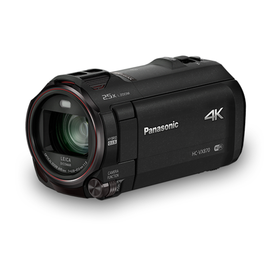
Summarization of Contents
1 Safety Precautions
1.1 General Guidelines
Important safety notice and general guidelines for handling the equipment.
1.2 Leakage Current Cold Check
Procedure for checking leakage current when the unit is unplugged.
1.3 Leakage Current Hot Check
Procedure for checking leakage current when the unit is plugged in.
2 Warning
2.1 Prevention of Electrostatic Discharge (ESD) to Sensitive (ES) Devices
Guidelines to prevent damage from electrostatic discharge to sensitive electronic components.
2.2 How to Recycle the Lithium Ion Battery (U.S. Only)
Instructions on how to properly recycle lithium-ion batteries in the US.
3 Service Navigation
3.1 Introduction
Introduction to service manuals and how to use them.
3.2 General Description About Lead Free Solder (PbF)
Description of lead-free solder, its composition, and handling.
3.3 How to Define the Model Suffix (NTSC or PAL model)
Explanation of model suffixes and their meaning.
6 Service Mode
6.1 Model/Destination Settings
Procedure to select model/destination settings within the service mode.
6.2 Lock Search and Error History Indication
Procedure to display lock search and error history in service mode.
6.3 Power ON Self Check Result Display
How to display the Power ON self check results in service mode.
6.4 Adjustment function for the Service
Details on adjustment functions available for service personnel.
6.5 Restore the backed up adjustment data
Procedure to restore adjustment data from an SD card.
6.6 Touch Panel Calibration
Procedure for calibrating the touch panel in service mode.
6.7 NFC Initialization (except HC-V760)
Procedure for initializing the NFC chip and settings.
7 Service Fixture & Tools
7.1 When Replacing the Main P.C.B.
Guidance on tools and fixtures needed for main PCB replacement.
7.2 Service Position
Describes service positions and uses of extension cables.
8 Disassembly and Assembly Instructions
8.1 Disassembly Flow Chart for the Unit
Flow chart illustrating the disassembly steps for the unit.
8.2 PCB Location
Diagrams showing the location of various PCBs within the unit.
8.3 Disassembly Procedure for the Unit
Step-by-step procedure for disassembling the unit.
8.3.1 Removal of the Side Case-L Unit
Detailed steps for removing the Side Case-L unit.
8.3.2 Removal of the Top Case, Top Operation
Procedure for removing the top case and top operation parts.
8.3.3 Removal of the Front Case Unit
Steps for removing the front case unit.
8.3.4 (except HC-V760) Removal of the NFC P.C.B. Unit, Wi-Fi P.C.B.
Procedure to remove NFC and Wi-Fi PCBs, excluding HC-V760.
8.3.5 Removal of the Photo Light DRV P.C.B.
Steps for removing the Photo Light Driver PCB.
8.3.6 Removal of the Wi-Fi Frame Unit, Lens Frame Unit, Barrier Motor Unit
Procedure to remove Wi-Fi frame, lens frame, and barrier motor units.
8.3.7 Removal of the Camera Lens Unit
Steps for removing the camera lens unit.
8.3.8 Removal of the Main P.C.B., SD Holder P.C.B.
Procedure to remove the Main PCB and SD Holder PCB.
8.3.9 (HC-WX970M/VX870M/V770M only) Removal of the ESD P.C.B. Unit
Procedure to remove the ESD PCB Unit for specific models.
8.3.10 Removal of the BR Frame Unit, Speaker, LCD Unit
Steps for removing the BR Frame Unit, Speaker, and LCD Unit.
8.3.11 Removal of the Batt. Catcher P.C.B.
Procedure to remove the Battery Catcher PCB.
8.3.12 (HC-WX970/WX979/WX970M) Removal of the LCD Hinge Unit, Sub Camera Unit
Procedure to remove LCD Hinge and Sub Camera Units.
8.3.13 (HC-VX870/VX878/V770/V777/V770M/V760) Removal of the LCD Hinge Unit
Procedure to remove the LCD Hinge Unit for specific models.
8.3.14 Removal of the Monitor P.C.B., LGP Unit, LCD
Steps for removing the Monitor PCB, LGP Unit, and LCD.
8.3.15 Removal of the Mic P.C.B.
Procedure to remove the Microphone PCB.
8.3.16 Removal of the Front Base, Barrier R, Barrier F, Photo Light P.C.B.
Steps for removing Front Base, Barrier R/F, and Photo Light PCB.
8.3.17 Removal of the Front Ring, Hood Piece
Procedure to remove the front ring and hood piece.
8.3.18 Removal of the Front Case, Front Ornament Unit, Mic Case Unit
Steps for removing Front Case, Ornament Unit, and Mic Case Unit.
8.3.19 Removal of the Kurupon Unit, Front P.C.B.
Procedure to remove the Kurupon Unit and Front PCB.
8.3.20 Removal of the MOS Unit
Steps for removing the MOS Unit.
8.3.21 (HC-WX970/WX979/WX970M/VX870/VX878/VX870M only) Removal of the IR Kudou Unit
Procedure to remove the IR Kudou Unit for specific models.
8.3.22 Removal of the 2nd Stepping Motor
Steps for removing the 2nd stepping motor.
8.3.23 Removal of the 3rd Stepping Motor
Procedure to remove the 3rd stepping motor.
8.3.24 Removal of the 4th Stepping Motor
Steps for removing the 4th stepping motor.
9 Measurements and Adjustments
9.1 Electric Adjustment
Details on electric adjustment procedures and required jigs.
9.1.1 About Light Box
Information about using the VFK1164TDVLB Light Box.
9.1.2 Adjustment Items
List of adjustment items and their corresponding settings.
9.1.3 Adjustment Procedure
Step-by-step procedure for performing adjustments in service mode.
10 Factory Setting
10.1 How To Turn On The Factory Settings?
Procedure for accessing and enabling factory settings.
10.2 What Is The Factory Settings?
Explanation of the functions and purpose of factory settings.


Need help?
Do you have a question about the HC-VX870EF and is the answer not in the manual?
Questions and answers