Table of Contents
Advertisement
Quick Links
Miniseries Ozone Generator Troubleshooting
Please run through all troubleshooting sections to insure proper operation, the
more common symptoms are listed here:
System does not turn on or off when it is supposed to. No lights are
illuminated.
Normally the system will respond by a vacuum switch signal to turn off
•
and on when the vacuum of the venturi is present or not. If there is not
enough or no vacuum at the venturi the system will not respond properly.
Look to the Gauge Readings section of this troubleshooting guide for
o
assistance with this issue, check for leaks and proper gauge readings
and adjust the vacuum switch if needed.
This could be a power supply issue if the unit never turns on, as opposed
•
to never turning off.
o
Look to the Display Lights section for assistance with no lights being
illuminated.
Some lights are illuminated, but none are ozone lights.
This is usually a control or circuit board issue.
•
Look to the Display Lights section for assistance.
o
Low ozone output is suspected / Crystals are pink or white in color.
This is normally resolved with maintenance, but there are a few hardware
•
components to check for proper operation.
Look to the Colored Crystals section for assistance.
o
Troubleshooting Contents:
Display Lights - These LEDs will show the current status of the system and if it is generating ozone
at this moment.
Colored Crystals - In "/AD" systems, colored silica gel crystals are visible through the cover. The
"good" color is blue. In non-/AD systems, the inline particulate filter contains silica gel
beads. We're looking for these beads to be blue in color.
Gauge Readings - If installed, the gauge assembly can tell you the air from the generator is being
drawn into the water at the proper rate. Additionally, the vacuum reading verifies that ambient air is
not blending in at any point, which would reduce the system's effectiveness.
Hardware Inspections - The end of the guide goes over inspection of important components and
inspection in the case of water damage.
Before you start:
When adjusting or replacing components within the ozone generator, turn the system off and deny the power cord connection either at the ozone
•
generator or at the outlet.
When observing operation of boards or other components with the cover removed, a cover safety switch will have to be manually triggered for
•
operation.
When operating with the cover removed, do not come near or in contact with the white wire that connect to the top of a reaction chamber.
o
Do not install or remove circuit boards while the unit is powered. If the unit's model ends in /AD, be aware that at least one of the air dryer
chamber cylinders may be very hot, do not touch them.
Look to the inside of the cover for the peg that normally presses the switch down and install a pencil or something similar to depress the
o
switch to operate with the cover removed.
If you wish to still have display lights illuminated during operation with the cover off the unit, leave the wires connected to the cover and
o
simply hold it elevated, keeping sure to not touch the chassis to the upper area of the reaction chamber. Otherwise, disconnect wires from
the cover (ribbon cable from the control board and ground wire from the cover).
Read through each troubleshooting section before performing the tests to insure the tests are performed correctly the first time.
•
A multi-meter is recommended for some tests, but is not vital to troubleshooting.
•
Buy spare parts on www.cleanwaterstore.com Call us 1-888-600-5426
Email us: support@cleanwaterstore.com
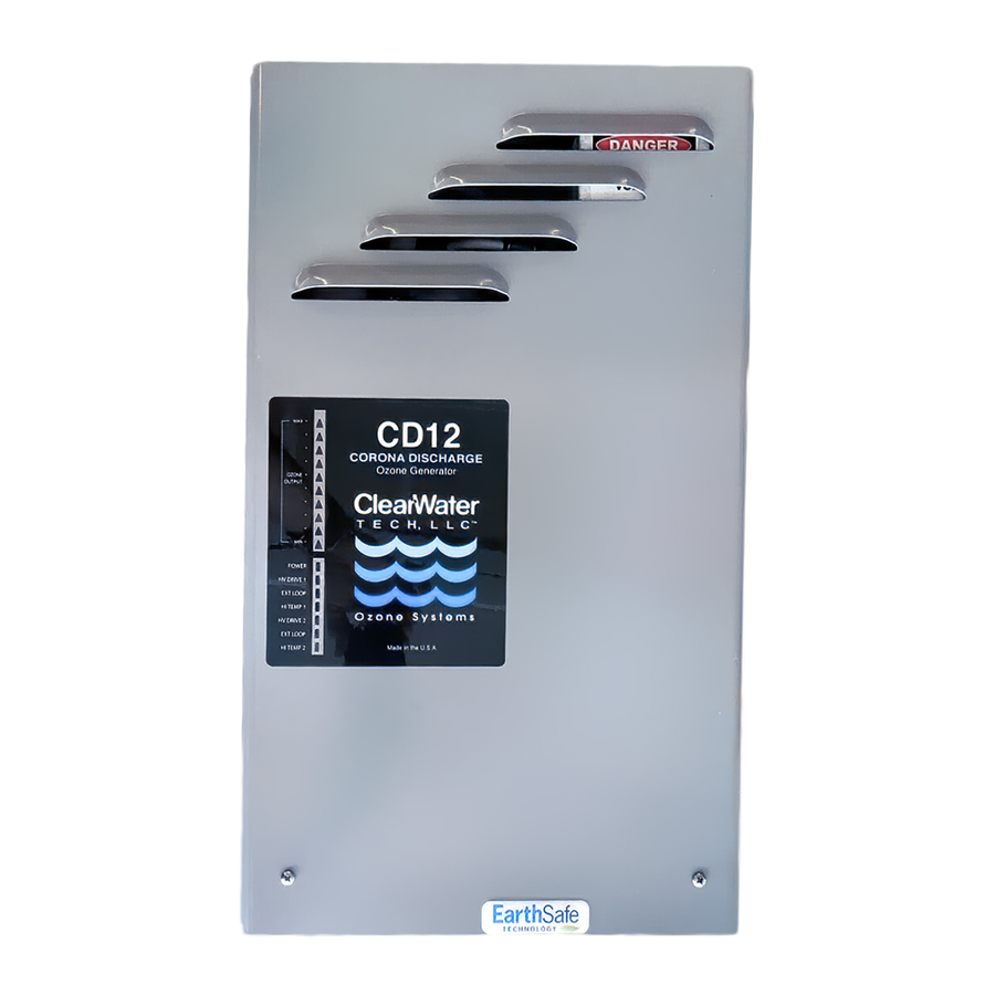
FOR USE WITH CD10, CD10/AD, CD12 & CD12/AD
Pictured is the CD12/AD, the
components of other Miniseries
systems will be similar, and are
often interchangeable.
110613
Page 1
Advertisement
Table of Contents

Related Manuals for CleanWater Tech CD12

Summary of Contents for CleanWater Tech CD12
- Page 1 Miniseries Ozone Generator Troubleshooting FOR USE WITH CD10, CD10/AD, CD12 & CD12/AD Please run through all troubleshooting sections to insure proper operation, the more common symptoms are listed here: System does not turn on or off when it is supposed to. No lights are illuminated.
-
Page 2: Display Lights
Miniseries Ozone Generator Troubleshooting FOR USE WITH CD10, CD10/AD, CD12 & CD12/AD Display Lights The lights to focus on are the upper set of ten lights labeled "Ozone Output" these are the usually the red triangle lights. If these lights are illuminated, the generator is generating ozone*. - Page 3 Miniseries Ozone Generator Troubleshooting FOR USE WITH CD10, CD10/AD, CD12 & CD12/AD Confirm the black, plastic on/off switch of the unit is switched to “on” - the switched should be pressed down on the right side. • The switch is located next to the power cord connection. Confirm the cover safety switch is depressed (even if the cover is currently on), see Before you start section earlier in the guide.
- Page 4 Miniseries Ozone Generator Troubleshooting FOR USE WITH CD10, CD10/AD, CD12 & CD12/AD If the ozone generator operates fine, but the EXT LOOP light only turns off when manually jumped out, follow the wire normally connected to the external loop connection and investigate why it is not closing the circuit properly. Normally this is connecting to a vacuum switch in t he case of an “/AD”...
- Page 5 Miniseries Ozone Generator Troubleshooting FOR USE WITH CD10, CD10/AD, CD12 & CD12/AD Some or all of ozone output lights illuminated, but no control of ozone output: This is usually coupled with no ozone output detected when blowing air through the unit. This is a display board issue.
- Page 6 Miniseries Ozone Generator Troubleshooting FOR USE WITH CD10, CD10/AD, CD12 & CD12/AD Ozone generator operates normally for a random length of time, and then the display lights shut off (unit turns off) Both of these symptoms are the affect of the motherboard (power supply) shutting off or being reset repeatedly. Usually (95% of the time) replacement of the motherboard will resolve the issue.
- Page 7 Miniseries Ozone Generator Troubleshooting FOR USE WITH CD10, CD10/AD, CD12 & CD12/AD Colored Crystals Blue silica gel crystals are installed in each model ozone generator. CD10/AD units also have a chamber visible through the cover that has mixed blue and white crystals. This is at times referred to as indicating desiccant media.
- Page 8 Miniseries Ozone Generator Troubleshooting FOR USE WITH CD10, CD10/AD, CD12 & CD12/AD Steps to set up or recalibrate airflow for the ozone system: Notes: If the gauge readings show the needle in the green range and the SCFH ball is in the range appropriate for the ozone generator, these steps are unnecessary.
- Page 9 Miniseries Ozone Generator Troubleshooting FOR USE WITH CD10, CD10/AD, CD12 & CD12/AD No suction at venturi Venturi injectors generate suction by creating a pressure differential upstream and downstream from where it is installed. There are many different models of venturi that operate at different pressures and flow rates. The bypass part of our venturi manifolds has a ball valve installed that allows us to adjust the flow rate through the venturi and thus the amount of suction.
- Page 10 Miniseries Ozone Generator Troubleshooting FOR USE WITH CD10, CD10/AD, CD12 & CD12/AD Notes on the vacuum break assembly: This assembly was designed to keep water from flowing up the waterline and into the ozone generator. It does have a drain port open to atmospheric air. Verify that air is not using the lower half of the assembly, as it represents a leak of some kind.
- Page 11 Miniseries Ozone Generator Troubleshooting FOR USE WITH CD10, CD10/AD, CD12 & CD12/AD Notes on the vacuum switch not responding: This switch is sensitive to low levels of vacuum. If the system vacuum levels are set to the edge of green (-3”Hg), the vacuum switch may not release properly when the -3”Hg vacuum goes to zero. If the vacuum gauge can be adjusted to the left-side of green (-8”Hg), and maintain proper SCFH readings;...
-
Page 12: Hardware Inspection
Miniseries Ozone Generator Troubleshooting FOR USE WITH CD10, CD10/AD, CD12 & CD12/AD Hardware Inspection Follow this brief guide on verifying the subcomponents of a system are healthy when performing maintenance, general inspection, or assessing damage of a system. In this section: Water damage •... - Page 13 Miniseries Ozone Generator Troubleshooting FOR USE WITH CD10, CD10/AD, CD12 & CD12/AD Reaction chamber inspection Full disassembly and maintenance instructions can be found in the manual for the ozone generator as well as the maintenance instruction sheets. Exterior inspection: Confirm the white high voltage wire that connects to the top of a reaction chamber is not coming in •...
-
Page 14: Air Dryer
Miniseries Ozone Generator Troubleshooting FOR USE WITH CD10, CD10/AD, CD12 & CD12/AD Air dryer CD10/AD and CD12/AD only. The internal air dryer has two heating elements, a solenoid valve and a circuit board that controls its operation. The heating elements and the controls of the air dryer control board are rarely ever an issue.
Need help?
Do you have a question about the CD12 and is the answer not in the manual?
Questions and answers