Sign In
Upload
Download
Table of Contents
Contents
Add to my manuals
Delete from my manuals
Share
URL of this page:
HTML Link:
Bookmark this page
Add
Manual will be automatically added to "My Manuals"
Print this page
×
Bookmark added
×
Added to my manuals
Manuals
Brands
Strautmann Manuals
Utility Vehicle
Aperion 2401
Translation of the original operating instructions
Strautmann Aperion 2401 Translation Of The Original Operating Instructions
Conveyor belt wagon
Hide thumbs
1
2
3
4
5
Table Of Contents
6
7
8
9
10
11
12
13
14
15
16
17
18
19
20
21
22
23
24
25
26
27
28
29
30
31
32
33
34
35
36
37
38
39
40
41
42
43
44
45
46
47
48
49
50
51
52
53
54
55
56
57
58
59
60
61
62
63
64
65
66
67
68
69
70
71
72
73
74
75
76
77
78
79
80
81
82
83
84
85
86
87
88
89
90
91
92
93
94
95
96
97
98
99
100
101
102
103
104
105
106
107
108
109
110
111
112
113
114
115
116
117
118
119
120
121
122
123
124
125
126
127
128
129
130
131
132
133
134
135
136
137
138
139
140
141
142
143
144
145
146
147
148
149
150
151
152
153
154
155
156
157
158
159
160
161
162
163
164
165
166
167
168
169
170
171
172
173
174
175
176
177
178
179
180
181
182
183
184
185
186
187
188
189
190
191
192
193
194
195
196
197
page
of
197
Go
/
197
Contents
Table of Contents
Bookmarks
Table of Contents
Table of Contents
1 User Information
Purpose of Document
Keeping of Operating Instructions
Location Details in the Operating Instructions
Applied Modes of Specification
Applied Terms
Activity-Related Safety Instructions and Important Information
2 Product Description
General Overview of the Machine
Chassis
Bogie Tandem Chassis
Tandem /Tridem Chassis with Hydraulic Travelling Height Adjustment
Tandem / Tridem Chassis with Hydro-Pneumatic Suspension
Drawgear
Towing Eye
Brake System
Dual-Line Compressed-Air Brake System
Dual-Line Compressed-Air Brake System with Mechanical Automatic Load-Sensitive Brake (ALB) Regulator
Dual-Line Compressed-Air Brake System with Hydraulic Automatic Load-Sensitive Brake Pressure (ALB) Regulator
Hydraulic Service Brake System
Braking Axle
Steering Axle
Passive Steering Axle
Steering Axle for Electro-Hydraulic Forced Steering Axle System SES
Hydraulic System
Marking of Hydraulic Supply Lines
Supply Lines between Tractor and Machine
Electro-Hydraulic Control Block
Load-Sensing Hydraulic System
Transport Floor
Tailgate
Tailgate with Grain Gate
Tailgate with Potato Gate
Supporting Leg
Mechanical Supporting Leg
Hydraulic Supporting Leg
Mechanical Supporting Leg in Combination with Hydraulic Drawbar Suspension
Underride Guard
Mechanically Folding Underride Guard
Hydraulically Folding Underride Guard
Beaters
Extensions
Rigid Extensions
Folding Extensions
Telescoping Extensions
Front Panel
Covering System
Traffic-Related Equipment
Type Plate
Technical Data
General Data
Tyre Pressure
Required Tractor Equipment
2.18.3.1 Electrical System
2.18.3.2 Hydraulic System
2.18.3.3 Control Devices with Direct Control
2.18.3.4 Control Devices with E-Control
Brake System
3 Safety Instructions
Correct Use
Organisational Measures
User's Obligation
Operator's Obligation
Qualification of Staff
Product Safety
Hazardous Area and Dangerous Spots
Risks When Handling the Machine
Safety and Protective Devices
Structural Alterations
Spare and Wearing Parts, Auxiliary Materials
Warranty and Liability
Basic Safety Instructions
General Safety and Accident Prevention Instructions
Hitch and Unhitch Machine
Use of Machine
Transport Journeys
Hydraulic System
Electrical System
Propeller Shafts
Hitched Machines
Brake System
Compressed-Air Brake System
Tyres
Cleaning, Service, Maintenance and Trouble-Shooting
Risks Due to Residual Energy
Warning and Instruction Signs
Warning Signs
Instruction Signs
Placing of Warning and Instruction Signs
Risks Due to Non-Observance of Safety Instructions
4 Loading and Unloading of Machine
Loading and Unloading by Means of a Tractor
Loading and Unloading by Means of a Crane
5 Commissioning
Road Traffic Regulations
Road Traffic Regulations in Germany
Check Tractor's Compatibility
Preconditions for the Operation of Tractors with Rigid-Drawbar Trailers
Combination Options of Coupling Devices and Drawgears
Calculate Actual D Value for Combination to be Coupled
Calculate Tractor's Admissible Towing Capacity
Secure Tractor and Machine against Accidental Starting and Rolling
Parking Brake
Release Parking Brake
Apply Parking Brake
Brake System
Lift / Lower Supporting Leg
Lift Hydraulic Supporting Leg to Transport Position
Lower Hydraulic Supporting Leg to Support Position
Lift Mechanical Supporting Leg to Transport Position
Lower Mechanical Supporting Leg to Support Position
Lift Mechanical Supporting Leg in Combination with Hydro-Pneumatic Drawbar Suspension to Transport Position
Lower Mechanical Supporting Leg in Combination with Hydro-Pneumatic Drawbar Suspension to Support Position
Adjust Length of Propeller Shaft to Tractor
Hitch Machine
Connect Hydraulic Hose Pipes
Open Hydraulic System
Load-Sensing Mode
Couple Drawgear
Tow-Hook (Hitch Hook) and Drawbar Lug (Hitch Ring)
Draw Pin (Piton-Fix) and Drawbar Lug (Hitch Ring)
Ball-Type Coupling and Shell
Couple Forced Steering Axle
Connect Brake System
Connect Dual-Line Service Brake System
Connect Hydraulic Brake System
Connect Emergency Brake Valve
Couple Propeller Shaft
Unhitch Machine
Uncouple Drawgear
Tow-Hook (Hitch Hook) and Drawbar Lug (Hitch Ring)
Draw Pin (Piton-Fix) and Drawbar Lug (Hitch Ring)
Ball-Type Coupling and Shell
Disconnect Hydraulic Hose Pipes
Disconnect Brake System
Disconnect Dual-Line Service Brake System
Disconnect Hydraulic Brake System
Disconnect Hydraulic Brake System with Emergency Brake Valve
Uncouple Propeller Shaft
Manoeuvre Unhitched Machine by Means of a Manoeuvring Vehicle
Mount/Set Extension Sections on Cargo Space
Mount Extensions in Rigid Position
Mount Extensions in Folding Position
Retract and Extend Telescoping Extensions
Set Tailgate
Beaters
Mount Beaters
Remove Beaters
Switch Potato Gate over
Insert Inspection Glasses
6 Operation
Operation with Direct Control and Forced Steering Axle System
Operation Via E-Control
Functions and Their Symbols
Switch Control Set On/Off/Switch Road Travel Mode on
Switch Work Lights on / off
Lift/Lower Telescopic Extension
Open/Close Cargo Space Cover
Open/Close Front Panel
Close/Open Tailgate
Power/Reverse Transport Floor in Discharging Direction
Adjust Transport Floor Speed
External Operation for Transport Floor Feed
6.2.2.10 Lock/Unlock Steering Axle
Steering
Unlock Passive Steering Axle with Direct Operation Function
Lock Passive Steering Axle with Direct Operation Function
Operation of Steering Computer
Access to Steering Computer
Operating and Display Elements of Steering Computer
Error Log, Forced Steering Axle System
7 Use of Machine
Transport Journeys
Charge Machine
Discharge Machine
Hydraulic Transport Floor Drive / Without Beaters
Hydraulic Transport Floor Drive / with Beaters
8 Service and Maintenance of Machine
Lock Tailgate
Service and Maintenance Plan - Overview
Maintenance of Axles
Lubricate Knuckle Arm Bearing
Lubricate Spherical Bearings of Locking / Steering Cylinders
Lubricate Brake Shaft Bearing
Lubricate Standard Slack Adjuster
Lubricate Automatic Slack Adjuster
Tighten Wheel Nuts
Tightening Torques of Wheel Nuts
Check Clearance of Wheel Hub Bearing
Check Brake Linings
Check Brake
Check and Adjust Standard Slack Adjuster
Check Automatic Slack Adjuster
Maintenance of Hydraulic Chassis
Lubricate Bearing of Dash Pots
Drain Condensate
Check/Top up Hydraulic Oil of Dash Pots
Adjust Travelling Height Via Three-Way Cock
Cleaning Work
Cleaning by Means of Pressure Washer / Steam Blaster
Lubrication Work
Central Lubrication
Quantities When Filled and Change Intervals
Lubrication Plan of Aperion 2101
Lubrication Plan of Aperion 2401 / 3401
Check / Top up Gear Lubricant Oil
Feed Gearing
Angular Gear
Transport Floor
Retighten Transport Floor
Adjust Conveyor Belt
Check/Clean Brush Roller
Adjust Stripper
Beaters
Check/Retighten/Lubricate Roller Chain Tension
Hydraulic System
Depressurise Hydraulic System
Marking of Hydraulic Hose Pipes
Inspection Criteria for Hydraulic Hose Pipes
Replace Hydraulic Filter
Brake System
Check/Clean In-Line Filters of Compressed-Air Brake System
Drain Compressed-Air Reservoir of Compressed-Air Brake System
9 Remedy of Malfunctions
List of Malfunctions, Hydraulic System
List of Malfunctions, Electrical System
Emergency Manual Operation in Case of Failure of Electrical System
Emergency Manual Operation of Electro-Hydraulic Forced Steering Axle System SES
10 Disassembly / Disposal
11 Circuit Diagrams
Hydraulic Circuit Diagram - Tandem - Direct Control
Hydraulic Circuit Diagram - Tandem - Operation Via Control Set
Hydraulic Circuit Diagram - Tridem - Direct Control
Hydraulic Circuit Diagram - Tridem - Operation Via Control Set
Electronic Circuit Diagram - Control Set
Electronic Circuit Diagram - Forced Steering Axle System
Connection, Lighting
Advertisement
Quick Links
Download this manual
Translation of the Original
Operating Instructions
Conveyor belt wagon
Aperion 2101, Aperion 2401, Aperion 3401
72400901 a.000
04.18
Table of
Contents
Previous
Page
Next
Page
1
2
3
4
5
Advertisement
Table of Contents
Need help?
Do you have a question about the Aperion 2401 and is the answer not in the manual?
Ask a question
Questions and answers
Related Manuals for Strautmann Aperion 2401
Utility Vehicle Strautmann Giga-Trailer 2246 Operating Instructions Manual
Chopper trailer (39 pages)
Utility Vehicle Strautmann Giga-Trailer 2246 DO Operating Instructions Manual
Chopper trailer (39 pages)
Utility Vehicle Strautmann Aperion 2101 Translation Of The Original Operating Instructions
Conveyor belt wagon (197 pages)
Utility Vehicle Strautmann Aperion 3401 Translation Of The Original Operating Instructions
Conveyor belt wagon (197 pages)
Utility Vehicle Strautmann Giga-Trailer 1840 Operating Instructions Manual
Chopper trailer (39 pages)
Summarization of Contents
User Information and Document Guidance
Purpose, Keeping, and Location of Instructions
Explains the purpose, proper keeping, and location details of the operating instructions.
Specification Modes, Terms, and Figure Conventions
Details applied modes, lists, position numbering, figure lines, and applied terms.
Safety and Information Symbols
Explains the meaning and usage of WARNING, IMPORTANT, and INFORMATION symbols.
Product Description
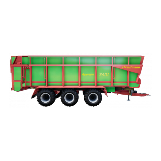
General Overview and Machine Components
Provides a comprehensive overview and identification of essential machine elements with illustrations.
Chassis Types and Axles
Details chassis types (bogie tandem, tandem/tridem) and braking axles, including hydraulic adjustments.
Drawgear, Towing Eye, and Brake System
Describes drawgear options, towing eye, and the components of the service brake system.
Steering Axle Systems
Covers passive and electro-hydraulic forced steering axle systems (SES), including operational details.
Hydraulic System and Supply Lines
Details the hydraulic system operation, supply lines, and the electro-hydraulic control block.
Transport Floor, Tailgate, and Supporting Leg
Explains the function and operation of the transport floor, tailgate, and supporting leg systems.
Underride Guard, Beaters, and Extensions
Covers the underride guard, optional beaters, and extensions, including their mounting and function.
Front Panel, Covering System, and Traffic Equipment
Explains the front panel, covering system, and the importance of traffic-related equipment for road travel.
Type Plate and Technical Data
Explains the type plate information and provides detailed general technical data for machine models.
Tyre Pressure and Tractor Equipment
Details required tyre pressures and essential tractor equipment for electrical and hydraulic systems.
Safety Instructions
Correct Use, Organisational Measures, and Product Safety
Defines intended use, organizational measures, and product safety aspects including hazardous areas and risks.
Safety and Protective Devices
Details the location and importance of safety and protective devices, requiring daily checks.
General Safety and System Procedures
Provides fundamental safety rules, accident prevention, and safety procedures for hydraulic, electrical, and propeller shaft systems.
Operational Safety and Maintenance Safety
Outlines safety measures for transport journeys, machine operation, and general safety for maintenance work.
Brake System, Tyre, and Cleaning Safety
Covers safety for brake systems, tyre handling, and cleaning procedures, emphasizing precautions.
Warning Signs and Non-Compliance Risks
Guides on understanding warning signs and summarizes consequences of not following safety instructions.
Risks from Non-Observance
Summarizes consequences of not following safety instructions, including risks to people and environment.
Loading and Unloading
Tractor and Crane Loading/Unloading Procedures
Details safe procedures for loading/unloading using tractors or cranes, including compatibility checks.
Commissioning
Road Traffic Regulations and Tractor Compatibility
Outlines road traffic regulations and crucial checks for tractor compatibility, including weight ratings and brake tests.
Coupling, Towing Capacity, and Hitching Procedures
Explains coupling options, towing capacity calculations, and essential steps for hitching the machine safely.
System Connections and Brake System Setup
Details procedures for connecting hydraulic, brake, and propeller shaft systems, including safety precautions.
Forced Steering Axle Coupling and Brake System Connection
Covers coupling the forced steering axle and connecting the brake system, emphasizing safety.
Unhitching Procedures and System Disconnection
Details the safe procedure for unhitching the machine, including disconnecting all systems and ensuring space.
Operation
Machine Operation Modes and Control Sets
Explains machine operation via tractor controls or optional control sets, covering direct control and E-control.
Control Set Functions, Symbols, and Steering Operations
Shows symbols and explains functions for control set elements, including steering axle locking/unlocking.
Steering Computer Operations and Error Handling
Details steering computer access, operating elements, display messages, and error logging procedures.
Service and Maintenance
Service Plan Overview and Axle Maintenance
Presents a maintenance plan overview and details axle lubrication and maintenance procedures.
Component Lubrication and Hydraulic Chassis Maintenance
Covers lubrication of various components and hydraulic chassis maintenance, including oil checks.
Cleaning Procedures and Filter Replacement
Details cleaning methods, especially with pressure washers, and the procedure for replacing hydraulic filters.
Brake System and Gearbox Maintenance
Covers inspection of brake system filters and maintenance of gearboxes, including oil checks.
Malfunction Remedy and Disposal
Hydraulic and Electrical Malfunction Troubleshooting
Provides troubleshooting guides for hydraulic and electrical system malfunctions, listing causes and remedies.
Emergency Manual Operations and Disassembly/Disposal
Explains emergency manual operations and guidelines for safe disassembly and disposal of the machine.
Circuit Diagrams
Hydraulic Circuit Diagrams (Tandem & Tridem)
Presents hydraulic circuit diagrams for tandem and tridem chassis, covering direct control and control set operations.
Electronic Circuit Diagrams
Shows electronic circuit diagrams for the control set and forced steering axle system, detailing connections.
Connection and Lighting Diagrams
Details pin assignments and wire colors for lighting connections and general circuit diagram labels.
Table of Contents
Print
Rename the bookmark
Delete bookmark?
Delete from my manuals?
Login
Sign In
OR
Sign in with Facebook
Sign in with Google
Upload manual
Upload from disk
Upload from URL
Need help?
Do you have a question about the Aperion 2401 and is the answer not in the manual?
Questions and answers