Table of Contents
Advertisement
SERVICE MANUAL
Ver. 1.1 2014.04
The service manual of the mechanism deck, used in
this model, has been issued in a separate volume.
Please refer to the service manual of the MG-101
series for the mechanism deck information.
• The tuner and CD sections have no adjustments.
(MEX-GS610BT only)
FOR THE CUSTOMERS IN THE USA. NOT
APPLICABLE IN CANADA, INCLUDING IN THE
PROVINCE OF QUEBEC.
POUR LES CLIENTS AUX ÉTATS-UNIS. NON
APPLICABLE AU CANADA, Y COMPRIS LA
PROVINCE DE QUÉBEC.
(MEX-GS610BT only)
AUDIO POWER SPECIFICATIONS
CEA2006 Standard
Power Output: 17 Watts RMS × 4 at 4
Ohms < 1% THD+N
SN Ratio: 80 dBA
(reference: 1 Watt into 4 Ohms)
Tuner section
(
)
MEX-GS610BT
FM
Tuning range: 87.5 – 107.9 MHz
Antenna (aerial) terminal:
External antenna (aerial) connector
Intermediate frequency: 25 kHz
Usable sensitivity: 8 dBf
Selectivity: 75 dB at 400 kHz
Signal-to-noise ratio: 80 dB (stereo)
Separation: 50 dB at 1 kHz
Frequency response: 20 – 15,000 Hz
9-893-930-02
Sony Corporation
2014D33-1
©
2014.04
Published by Sony Techno Create Corporation
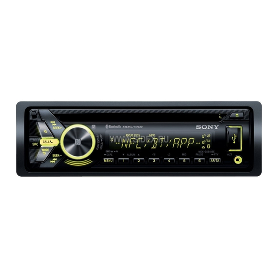
MEX-GS610BE/GS610BT/
Photo: MEX-GS610BT
Model Name Using Similar Mechanism
Mechanism Type
Optical Pick-up Name
SPECIFICATIONS
(MEX-N6050BT)
AM
Tuning range: 530 – 1,710 kHz
FM
Antenna (aerial) terminal:
Tuning range:
External antenna (aerial) connector
Intermediate frequency:
9,115 kHz or 9,125 kHz/5 kHz
Sensitivity: 26 μV
FM tuning step:
(MEX-GS610BE)
Antenna (aerial) terminal:
FM
Tuning range:
Intermediate frequency: 25 kHz
FM1/FM2: 87.5 – 108.0 MHz
Usable sensitivity: 8 dBf
(at 50 kHz step)
Selectivity: 75 dB at 400 kHz
FM3: 65 – 74 MHz (at 30kHz step)
Signal-to-noise ratio: 80 dB (stereo)
Antenna (aerial) terminal:
Separation: 50 dB at 1 kHz
External antenna (aerial) connector
Frequency response: 20 – 15,000 Hz
Intermediate frequency: 25 kHz
AM
Usable sensitivity: 8 dBf
Tuning range:
Selectivity: 75 dB at 400 kHz
Signal-to-noise ratio: 80 dB (stereo)
Separation: 50 dB at 1 kHz
AM tuning step:
Frequency response: 20 – 15,000 Hz
Antenna (aerial) terminal:
MW/LW
Tuning range:
Intermediate frequency:
MW: 531 – 1,602 kHz
LW: 153 – 279 kHz
Antenna (aerial) terminal:
Sensitivity: 26 μV
External antenna (aerial) connector
Intermediate frequency:
9,124.5 kHz or 9,115.5 kHz/4.5 kHz
Sensitivity: MW: 26 μV, LW: 45 μV
CD Player section
Signal-to-noise ratio: 120 dB
Frequency response: 10 – 20,000 Hz
87.5 – 108.0 MHz (at 50 kHz step)
Wow and flutter: Below measurable limit
87.5 – 108.0 MHz (at 100 kHz step)
Corresponding codec: MP3 (.mp3) and WMA (.wma)
87.5 – 107.9 MHz (at 200 kHz step)
USB Player section
50 kHz/100 kHz/200 kHz switchable
Interface: USB (High-speed)
Maximum current: 1 A (front), 2.1 A (rear)
External antenna (aerial) connector
The maximum number of recognizable tracks:
Corresponding codec:
531 – 1,602 kHz (at 9 kHz step)
530 – 1,710 kHz (at 10 kHz step)
9 kHz/10 kHz switchable
External antenna (aerial) connector
9,124.5 kHz or 9,115.5 kHz/4.5 kHz (at 9 kHz step)
9,115 kHz or 9,125 kHz/5 kHz (at 10 kHz step)
N6050BT
US Model
Canadian Model
MEX-GS610BT
E Model
MEX-N6050BT
Russian Model
MEX-GS610BE
CDX-G3000UE/G3000UP/
G3050UV
MG-101CF-188
DAX-25A
10,000
MP3 (.mp3), WMA (.wma) and WAV (.wav)
– Continued on next page –
AUDIO SYSTEM
Advertisement
Table of Contents

Related Manuals for Sony CDX-G3000UE


Summarization of Contents
SECTION 1 SERVICING NOTES
Handling Optical Pickup Block
Precautions for handling optical pick-up blocks to prevent electrostatic breakdown.
Laser Diode Emission Check Safety
Safety warning regarding laser diode emission checks to prevent eye injury.
Unleaded Solder Characteristics
Information on unleaded solder properties, melting temperature, and handling.
SECTION 2 GENERAL
Connection Diagram and Cautions
Diagrams and critical precautions for unit installation and wiring.
Subwoofer Easy Connection Example
Illustrates connecting a subwoofer using a rear speaker cord for simple setup.
SECTION 3 DISASSEMBLY
3-1. Disassembly Flow
Step-by-step procedure for disassembling the unit in a numerical order.
3-2. Mini Fuse and Cover Removal
Procedure for accessing and removing the unit's cover and mini fuse.
3-3. Sub Panel Assembly Removal
Procedure for removing and installing the sub panel assembly, including alignment.
3-4. CD Mechanism Deck Removal
Procedure for removing and installing the CD mechanism deck unit.
3-5. Connection Cable (Automobile) Procedure
Steps for disconnecting and connecting the automobile connection cable (CNC1).
3-6. Main Board Replacement
Procedure for replacing the main board, including related settings and checks.
3-7. Antenna BT (BT1) Replacement
Procedure for removing and installing the Bluetooth antenna (BT1).
SECTION 4 TEST MODE
Setting the Test Mode
Method for entering and exiting the unit's test mode for diagnostics.
Microphone Audio Loopback Test
Procedure to test microphone audio output through the speaker for hands-free function.
SECTION 5 DIAGRAMS
5-1. Block Diagram - Servo/BT/USB Section
Block diagram illustrating the servo, Bluetooth, and USB sections of the unit.
5-2. Block Diagram - Main Section
Block diagram of the main section, detailing signal paths and internal components.
5-3. Block Diagram - Panel/Power Supply Section
Block diagram showing the panel and power supply sections, including regulators.
Waveforms
Illustrations of various waveforms measured at different ICs on the main board.
5-4. Printed Wiring Boards - Main Section (1/2) (Type11)
Printed wiring board layout for the main board (component side, part 1).
5-5. Printed Wiring Boards - Main Section (2/2) (Type11)
Printed wiring board layout for the main board (conductor side, part 2).
5-6. Printed Wiring Boards - Main Section (1/2) (Type31)
Printed wiring board layout for the main board (component side, part 1, Type 31).
5-7. Printed Wiring Boards - Main Section (2/2) (Type31)
Printed wiring board layout for the main board (conductor side, part 2, Type 31).
5-8. Schematic Diagram - Main Section (1/4)
Schematic diagram of the main board, section 1 of 4, detailing regulator circuits.
5-9. Schematic Diagram - Main Section (2/4)
Schematic diagram of the main board, section 2 of 4, showing ICs and connections.
5-10. Schematic Diagram - Main Section (3/4)
Schematic diagram of the main board, section 3 of 4, illustrating power supply and control ICs.
5-11. Schematic Diagram - Main Section (4/4)
Schematic diagram of the main board, section 4 of 4, showing I/O and interface connections.
IC Block Diagrams
MAIN Board IC Block Diagrams
Block diagrams for key ICs on the main board, detailing their internal functions.
IC Pin Function Description
MAIN BOARD IC503 Pin Functions
Detailed pin function description for the system controller IC503 on the main board.
SECTION 6 EXPLODED VIEWS
6-1. Sub Panel Section Exploded View
Exploded view and parts list for the sub panel assembly of the unit.
6-2. Chassis Section Exploded View
Exploded view and parts list for the chassis section, including main board and cables.
Need help?
Do you have a question about the CDX-G3000UE and is the answer not in the manual?
Questions and answers