
Related Manuals for KRUEGER QFV


Summary of Contents for KRUEGER QFV
- Page 1 WWW.KRUEGER-HVAC.COM FAN POWERED TERMINAL UNITS INSTALLATION, START-UP, AND SERVICE INSTRUCTIONS FOR KRUEGER TERMINAL UNITS Models: KLPS, KLPS-D, KLPP, KQFS, KQFS-FA, KQFP, QFC, QFV...
-
Page 2: Table Of Contents
Step 3 - Power Wiring ..................11 Step 4 - System Setup And Calibration ............12 START-UP ....................14 General .......................14 Initial Start-Up Procedures................14 Balancing Krueger Fan Terminals ..............15 Speed Controller ....................20 Setting Fan Air Flow With EC Motors ............21 PNEUMATIC CONTROLS ................41 General .......................41... - Page 3 Fan Powered Terminal Units IOM TABLE OF CONTENTS ANALOG CONTROLS .................44 Installation And Balancing Procedures ............44 WATER VALVE INSTALLATION ..............46 Service ........................46 TROUBLESHOOTING .................48...
-
Page 4: Safety Note
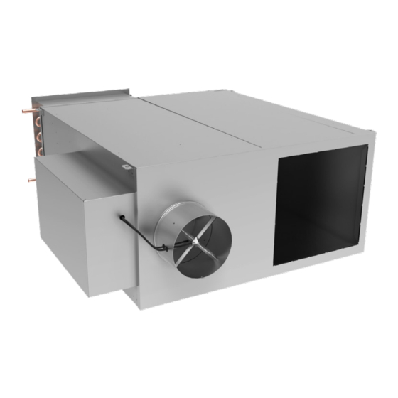
Do not lay uncrated units on end or sides. Do not stack uncrated units over 6 ft high. Do not handle control boxes by tubing connections or other external attachments. Table 1 shows component weights. Figure 2 - Series DOAS Fan Powered Terminal Unit (KLPS-D) - Page 5 Fan Powered Terminal Units IOM QFC (lbs.) HOT WATER ADD UNIT UNIT PNEUMATIC CONTROLS DDC OR ANALOG ELECTRIC SIZE WEIGHT CONTROLS ADD HEAT ADD 1-ROW 2-ROW QFV (lbs.) HOT WATER ADD UNIT UNIT PNEUMATIC CONTROLS DDC OR ANALOG ELECTRIC SIZE WEIGHT CONTROLS ADD HEAT ADD...
- Page 6 Fan Powered Terminal Units IOM KLPS (lbs.) HOT WATER ADD UNIT UNIT PNEUMATIC CONTROLS DDC OR ANALOG ELECTRIC SIZE WEIGHT CONTROLS ADD HEAT ADD 1-ROW 2-ROW KLPS-D (lbs.) UNIT WEIGHT WITH COOLING COIL HOT WATER ADD UNIT DDC CONTROLS ELECTRIC...
-
Page 7: Initial Inspection
ZERO CLERANCE FROM UNIT. CONNECTED DUCT AND/OR PLENUM. FIGURE 4 - Air Flow Label TO COMBUSTIBLE MATERIAL. WARRANTY FIGURE 3 - Fan Unit Label All Krueger-furnished items carry the standard Krueger warranty. UNIT IDENTIFICATION Each unit has 2 main labels attached to the casing. The CONTROL OPTIONS... -
Page 8: Analog Electronic Controls
SCR fan speed controller, 24-volt transformer, 2309 Cooling With Sequenced Fan & Up To 2 Stages Of Electric Heat and fan relay. Contact Krueger for information on mounting field-supplied controls. Cooling With Sequenced Fan & Up To 2 Stages Of Electric Heat & Automatic... -
Page 9: Installation
Shutdown And Unoccupied Heating A clearance of 36”* is recommended for line voltage motor TABLE 3A – Pneumatic Control Arrangements KLPS, KQFS & QFC controls and electric heat control access. High- voltage motor controls or electric heat control access is supplied PACKAGE NO. - Page 10 Fan Powered Terminal Units IOM supports, avoid areas where access is required to side INSTALL UNIT mounted controls, or side or bottom access doors. 1. Install field-supplied eyebolts, straphangers or bolt rod For best installation with trapeze supports, provide supports as desired. Figure 5 illustrates possible unit elastomeric material between unit and supports.
-
Page 11: Step 2 - Make Duct Connections
(if equipped). Electric heaters the distribution duct and the boot diffuser. provided by Krueger are balanced by kW per stage. The 2. Install the discharge duct. On units with electric heat, the installing electrician should rotate incoming electric recommended minimum distance of straight duct before service by phase to help balance overall building load. -
Page 12: Step 4 - System Setup And Calibration
FIELD ADJUSTMENT OF THE MAXIMUM AND MINIMUM demand. AIRFLOW SET POINTS The series fan powered terminals (KLPS, KQFS and QFC) are Each fan powered terminal unit is equipped with an airflow designed to provide a constant airflow to the space. The air... - Page 13 Fan Powered Terminal Units IOM VOLTS (DC), ANALOG CONTROLS INLET SNSOR ΔP INCHES W.G. (PASCALS) FIGURE 8 – Inlet Airflow Sensor CFM vs. Signal Chart...
-
Page 14: Start-Up
This factor is the K factor. 60 Hz, 115, 208/240, or 277 v, single-phase ac. electric Krueger inlet areas are shown in the table. The design air heat, the electric heat voltage may exceed the blower volume is shown in this table. It can be determined from motor voltage requirement. -
Page 15: Balancing Krueger Fan Terminals
Each control option has specific procedures required for cfm listed. balancing the unit, but some steps are common to all KLPS, KQFS & QFC units. The fan box adjustments described below must be made in conjunction with the adjustments... - Page 16 Fan Powered Terminal Units IOM 6. Cap the ‘T’ taps. 7. Reset the thermostat to a normal setting. NOTE: It is normal for the total airflow to the room to increase slightly in full cooling mode. TABLE 8 – KQFS Series Fan Terminal Unit PRIMARY AIR FLOW PCS MOTOR EC MOTOR...
- Page 17 3660 (2)3/4 3900 2100 (2)1 4550 1125 TABLE 9 – QFC Series Fan Terminal Unit TABLE 10 – KLPS Series Fan Terminal Unit PRIMARY AIR FLOW PCS MOTOR ECM MOTOR UNIT SIZE INLET SIZE MOTOR HP MAX FAN MIN FAN...
- Page 18 Fan Powered Terminal Units IOM TABLE 10A – KLPS-D Series Fan Terminal Unit PRIMARY AIR FLOW ECM MOTOR UNIT SIZE INLET SIZE MOTOR HP MAX FAN MIN FAN 1000 11625 1430 TABLE 10A – KLPS-D Series Fan Terminal Unit Note: Minimum Primary airflow may be 0 cfm.
- Page 19 Fan Powered Terminal Units IOM FIELD ADJUSTMENT OF MINIMUM AND MAXIMUM AIRFLOW min airflow has been adjusted, the total airflow with SET POINTS both fan and primary airflow should be checked. For sequences that call for the fan to start as the first stage Each parallel fan unit is equipped with a four quadrant of heat, the cooling minimum cfm can be verified at the multi-point center averaging airflow sensor that provides...
-
Page 20: Speed Controller
TO DECREASE THE FAN SPEED (RPM) SPEED CONTROLLER Turn the slotted adjustment on the controller clockwise Each Krueger fan powered air terminal unit is equipped with toward the “LO” marking. (Refer to Figure 9.) a fan SCR speed controller, located on the bottom of the control box. -
Page 21: Setting Fan Air Flow With Ec Motors
Fan Powered Terminal Units IOM SETTING FAN AIR FLOW WITH ECM MOTORS Several terminal unit models are available with ECM motors for easy balancing. These motors supply a determined amount of air regardless of static pressure from ductwork layout or air distribution. The ECM motors are programmed to provide a maximum CFM depending on model and unit size. - Page 22 Fan Powered Terminal Units IOM MANUAL % MANUAL % REMOTE 0-10Vdc (0-20mA) REMOTE 2-10Vdc (4-20mA) REMOTE 0-10Vdc (0-20mA) REMOTE 2-10Vdc (4-20mA) Point Display Point Display DC Signal (option 7) DC Signal (option 8) DC Signal (option 7) DC Signal (option 8) (option 6) (option 6) 1050...
- Page 23 Fan Powered Terminal Units IOM MANUAL % MANUAL % REMOTE 0-10Vdc (0-20mA) REMOTE 2-10Vdc (4-20mA) REMOTE 0-10Vdc (0-20mA) REMOTE 2-10Vdc (4-20mA) Point Display Point Display DC Signal (option 7) DC Signal (option 8) DC Signal (option 7) DC Signal (option 8) (option 6) (option 6) 2000...
- Page 24 Fan Powered Terminal Units IOM MANUAL % MANUAL % REMOTE 0-10Vdc (0-20mA) REMOTE 2-10Vdc (4-20mA) REMOTE 0-10Vdc (0-20mA) REMOTE 2-10Vdc (4-20mA) Point Display Point Display DC Signal (option 7) DC Signal (option 8) DC Signal (option 7) DC Signal (option 8) (option 6) (option 6) 2500...
- Page 25 Fan Powered Terminal Units IOM MANUAL % MANUAL % REMOTE 0-10Vdc (0-20mA) REMOTE 2-10Vdc (4-20mA) REMOTE 0-10Vdc (0-20mA) REMOTE 2-10Vdc (4-20mA) Point Display Point Display DC Signal (option 7) DC Signal (option 8) DC Signal (option 7) DC Signal (option 8) (option 6) (option 6) 1000...
- Page 26 Fan Powered Terminal Units IOM MANUAL % MANUAL % Dis- REMOTE 0-10Vdc (0-20mA) REMOTE 2-10Vdc (4-20mA) REMOTE 0-10Vdc (0-20mA) REMOTE 2-10Vdc (4-20mA) Point Point Display play (option 6) DC Signal (option 7) DC Signal (option 8) DC Signal (option 7) DC Signal (option 8) (option 6) 1000...
- Page 27 Fan Powered Terminal Units IOM MANUAL % MANUAL % REMOTE 0-10Vdc (0-20mA) REMOTE 2-10Vdc (4-20mA) REMOTE 0-10Vdc (0-20mA) REMOTE 2-10Vdc (4-20mA) Point Display Point Display DC Signal (option 7) DC Signal (option 8) DC Signal (option 7) DC Signal (option 8) (option 6) (option 6) 1100...
- Page 28 Fan Powered Terminal Units IOM MANUAL % MANUAL % REMOTE 0-10Vdc (0-20mA) REMOTE 2-10Vdc (4-20mA) REMOTE 0-10Vdc (0-20mA) REMOTE 2-10Vdc (4-20mA) Point Display Point Display DC Signal (option 7) DC Signal (option 8) DC Signal (option 7) DC Signal (option 8) (option 6) (option 6) 2550...
- Page 29 Fan Powered Terminal Units IOM MANUAL % MANUAL % REMOTE 0-10Vdc (0-20mA) REMOTE 2-10Vdc (4-20mA) REMOTE 0-10Vdc (0-20mA) REMOTE 2-10Vdc (4-20mA) Point Display Point Display DC Signal (option 7) DC Signal (option 8) DC Signal (option 7) DC Signal (option 8) (option 6) (option 6) 4550...
- Page 30 (13.0) (1.2) (5.0) (11.0) (12.8) (1.0) (4.8) (10.8) (12.6) (0.8) (4.6) (10.6) (12.5) (0.6) (4.5) (10.4) (12.3) (0.4) (4.3) (10.2) (12.2) (0.2) (4.2) CFM VALUES BELOW RECOMMENDED MINIMUM MAY AFFECT LIFE OF MOTOR. TABLE 22 KLPS Size 1 ECM CALIBRATION...
- Page 31 (13.0) (1.2) (5.0) (11.0) (12.8) (1.0) (4.8) (10.8) (12.6) (0.8) (4.6) (10.6) (12.5) (0.6) (4.5) (10.4) (12.3) (0.4) (4.3) (10.2) (12.2) (0.2) (4.2) CFM VALUES BELOW RECOMMENDED MINIMUM MAY AFFECT LIFE OF MOTOR. TABLE 23 KLPS Size 2 ECM CALIBRATION...
- Page 32 (13.0) (1.2) (5.0) (11.0) (12.8) (1.0) (4.8) (10.8) (12.6) (0.8) (4.6) (10.6) (12.5) (0.6) (4.5) (10.4) (12.3) (0.4) (4.3) (10.2) (12.2) (0.2) (4.2) CFM VALUES BELOW RECOMMENDED MINIMUM MAY AFFECT LIFE OF MOTOR. TABLE 24: KLPS Size 3 ECM CALIBRATION...
- Page 33 1045 (11.0) (12.8) (1.0) (4.8) 1026 (10.8) (12.6) (0.8) (4.6) 1007 (10.6) (12.5) (0.6) (4.5) (10.4) (12.3) (0.4) (4.3) (10.2) (12.2) (0.2) (4.2) CFM VALUES BELOW RECOMMENDED MINIMUM MAY AFFECT LIFE OF MOTOR. TABLE 25: KLPS Size 4 ECM CALIBRATION...
- Page 34 (13.0) (1.2) (5.0) (11.0) (12.8) (1.0) (4.8) (10.8) (12.6) (0.8) (4.6) (10.6) (12.5) (0.6) (4.5) (10.4) (12.3) (0.4) (4.3) (10.2) (12.2) (0.2) (4.2) CFM VALUES BELOW RECOMMENDED MINIMUM MAY AFFECT LIFE OF MOTOR. TABLE 26: KLPS Size 5 ECM CALIBRATION...
- Page 35 (13.0) (1.2) (5.0) (11.0) (12.8) (1.0) (4.8) (10.8) (12.6) (0.8) (4.6) (10.6) (12.5) (0.6) (4.5) (10.4) (12.3) (0.4) (4.3) (10.2) (12.2) (0.2) (4.2) CFM VALUES BELOW RECOMMENDED MINIMUM MAY AFFECT LIFE OF MOTOR. TABLE 27 KLPS-D Size 1 ECM CALIBRATION...
- Page 36 (13.0) (1.2) (5.0) (11.0) (12.8) (1.0) (4.8) (10.8) (12.6) (0.8) (4.6) (10.6) (12.5) (0.6) (4.5) (10.4) (12.3) (0.4) (4.3) (10.2) (12.2) (0.2) (4.2) CFM VALUES BELOW RECOMMENDED MINIMUM MAY AFFECT LIFE OF MOTOR. TABLE 28 KLPS-D Size 2 ECM CALIBRATION...
- Page 37 (13.0) (1.2) (5.0) (11.0) (12.8) (1.0) (4.8) (10.8) (12.6) (0.8) (4.6) (10.6) (12.5) (0.6) (4.5) (10.4) (12.3) (0.4) (4.3) (10.2) (12.2) (0.2) (4.2) CFM VALUES BELOW RECOMMENDED MINIMUM MAY AFFECT LIFE OF MOTOR. TABLE 29: KLPS-D Size 3 ECM CALIBRATION...
- Page 38 (13.0) (1.2) (5.0) (11.0) (12.8) (1.0) (4.8) (10.8) (12.6) (0.8) (4.6) (10.6) (12.5) (0.6) (4.5) (10.4) (12.3) (0.4) (4.3) (10.2) (12.2) (0.2) (4.2) CFM VALUES BELOW RECOMMENDED MINIMUM MAY AFFECT LIFE OF MOTOR. TABLE 30: KLPS-D Size 5 ECM CALIBRATION...
- Page 39 Fan Powered Terminal Units IOM MANUAL % MANUAL % REMOTE 0-10Vdc (0-20mA) REMOTE 2-10Vdc (4-20mA) REMOTE 0-10Vdc (0-20mA) REMOTE 2-10Vdc (4-20mA) Point Display Point Display DC Signal (option 7) DC Signal (option 8) DC Signal (option 7) DC Signal (option 8) (option 6) (option 6) (20.0)
- Page 40 Fan Powered Terminal Units IOM MANUAL % MANUAL % REMOTE 0-10Vdc (0-20mA) REMOTE 2-10Vdc (4-20mA) REMOTE 0-10Vdc (0-20mA) REMOTE 2-10Vdc (4-20mA) Point Display Point Display DC Signal (option 7) DC Signal (option 8) DC Signal (option 7) DC Signal (option 8) (option 6) (option 6) (20.0)
-
Page 41: Pneumatic Controls
Measure the volume of air flowing through the inlet 6. Start the blower motor by doing one of the following: using the calibration curve affixed to the unit. KLPS, KQFS & QFC Units: RANC Both RANC and DANO — Connect electrical power to the 1. - Page 42 DANC, RANC, DANO, RANO — Connect electrical power cooling and satisfied set point, the primary air damper to the blower motor controls. responds by proportional settings. Accessory coils, if sup-plied, are off. The KLPS, QFC & KQFS units only will be KLPP, KQFP & QFC Units:...
- Page 43 Fan Powered Terminal Units IOM inducing plenum air and mixing it with the cold primary point. Adjust the “RESET START” knob until the gage air. The KLPP, QFV & KQFP fan will not induce any plenum pressure begins to change slightly. Remove pressure air at this point.
-
Page 44: Analog Controls
The wiring schematic can also be found on the control 5202) operates on a 16 VDC power supply from the CSP 4702 sequence submittal found on the Krueger website. controller and outputs a 0 to 10 VDC signal on the AO1 and 5. - Page 45 Fan Powered Terminal Units IOM CFMs Per Inlet Size AO1 & AO2 Sensor Signl 0.00 0.03 1107 0.05 1565 0.08 1004 1917 0.10 1159 2214 0.13 1296 2475 0.15 1087 1420 2711 0.18 1174 1533 2928 0.20 1255 1639 3130 0.23 1331 1739...
-
Page 46: Water Valve Installation
Fan Powered Terminal Units IOM ANALOG CONTROL TROUBLESHOOTING WATER VALVE INSTALLATION The following troubleshooting guide is directed towards WARNING: Disconnect power before wiring or electrical single duct cooling applications, the same concepts can be shock and personal injury could result. applied to other configurations. - Page 47 Fan Powered Terminal Units IOM Brown to Brown to Brown to Capacitor Capacitor Capacitor White #12 to Terminal Block/ Diconnect Switch Black #12 Black #12 Black #12 White #12 to White #12 to Terminal Block/ Terminal Block/ Diconnect Switch Diconnect Switch Black #12 to SCR Controller Black #12 to...
-
Page 48: Troubleshooting
Fan Powered Terminal Units IOM TROUBLESHOOTING IF FAN MOTOR RUNS, EXCESSIVE NOISE: To remove the fan motor and wheel: 1. Make sure the blower, and all components have no 1. Disconnect motor wiring. Note connections. clearance problems and are securely attached. 2. - Page 50 YOUR RESOURCE FOR AIR DISTRIBUTION AND EQUIPMENT SOLUTIONS Let us know how we can assist you in your next building application. For more information, contact your local Krueger representative or visit us on the web at www.krueger-hvac.com. CRITICAL ROOM SOLUTIONS...
Need help?
Do you have a question about the QFV and is the answer not in the manual?
Questions and answers