
Related Manuals for NUVE TK 600


Summary of Contents for NUVE TK 600
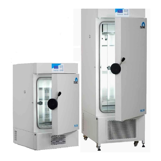
- Page 1 NÜVE SANAYİ MALZEMELERİ İMALAT VE TİCARET A.Ş. TK 120 / TK 252 / TK 600 CLIMATIC TEST CABINETS USER’S MANUAL Z14. K 25 258 Rev.No: 06 Rev.Date: 01/2016...
- Page 2 Fax : (00 90 312) 399 21 97 TEL: + (32) 2.732.59.54 e-mail: sales@nuve.com.tr WARRANTY CERTIFICATE 1. Nüve warrants that the equipment delivered is free from defects in material and workmanship. This warranty is provided for a period of two years. The warranty period begins from the delivery date.
-
Page 3: Table Of Contents
CONTENTS PAGE SECTION 1 USE AND FUNCTION SECTION 2 TECHNICAL SPECIFICATIONS 2.1. Technical Specifications Table 2.2. Temperature – Humidity Graph 2.3. Optional Accessories 2.4. General Presentation SECTION 3 INSTALLATION PROCEDURE 3.1. Lifting and Transport 3.2. Unpacking 3.3. Positioning 3.4. Prior to Operation 3.4.1. -
Page 4: Section 1 Use And Function
Lighting can be programmed depending on the requirement separately and two different illumination periods can be programmed. When all the lights are on the light intensity is about 6000 lux %10 for TK 120, 12000 lux %10 for TK 252 and 13000 lux ±... -
Page 5: Section 2 Technical Specifications
2. SECTION TECHNICAL SPECIFICATIONS 2.1. Technical Specifications Table TECHNICAL SPECIFICATIONS TK 120 TK 252 TK 600 -10ºC / +60ºC (lights off) Temperature Range without humidity 0ºC / +60ºC (lights on) Temperature Range with humidity +10ºC / +60ºC Temperature sensor Pt-100 4 –... -
Page 6: Optional Accessories
E 05 073 256 KB memory R 01 139 Shelf for TK 120/252 K 23 040 Shelf carrier for TK 120/252 (Should be ordered 2 pcs. for each shelf) R 01 146 Shelf for TK 600... -
Page 7: Section 3 Installation Procedure
3. SECTION INSTALLATION PROCEDURE 3.1. Lifting and Transport All lifting and transport must be carried out by using proper handling equipment. The equipment must be supported from underneath and never be turned over. 3.2. Unpacking Remove the packing box and the second nylon packing around the instrument. The below written items are provided with the equipment, please check them;... -
Page 8: Prior To Operation
3.4. Prior to Operation 3.4.1. Precautions and Limitations of Use Check that, There is no sample that can harm the chamber surface when heated, Liquids that may be dilate or samples that may be melt are not heated in sealed containers, ... -
Page 9: Section 4 Operating Principles
4. SECTION OPERATING PRINCIPLES 4.1. Switching On Turn on the unit by using the On-Off switch (Section 4.2) See that display activates. Learn the functions of display and control panel (Section 4.3) Set the program according to Section 4.3.2 then operate. WARNING: WHEN THE TEMPERATURE AND HUMIDITY LEVELS ARE HIGH INSIDE THE CHAMBER, DO NOT OPEN THE DOOR. -
Page 10: Display And Control Panel
4.3. Display and Control Panel F1, F2, F3, F4: Function keys that are used to perform the functions that correspond to those places. 1. START KEY: The program can be started to run by pushing START key. The LED of this key is on during the operation and flashes when the program is completed. -
Page 11: Setting And Operation Cycles
4.4.1. Setting the Language, Date and Time Switch on the cabinet. While there is “NUVE” logo on the screen, push “F1” to set language, date and time. LANGUAGE TUR ENG FRA Push “TAB” key to select language.... -
Page 12: Opening
4.4.2. Switching On Switch on the cabinet. “NUVE” logo will be on the screen for 5 seconds and display will go to stand-by position. 1.PROG: PLASTICS 1.STEP: 055.6 ºC STAND-BY POSITION 78 %RH DUE: 001:05 PT100 HELP 4.4.3. - Page 13 Save changes in memory by pressing “ENTER” key or Pass to the next window without saving the changes by pressing “NEXT” key. or Pass to the previous window without saving the changes by pressing “BACK” key. The next window is the window that you choice the condition of time counting. TIME STARTS TO COUNT BY ? START...
- Page 14 Select by using “TAB” key and selected parameter can be changed by using “INCREASE – DECREASE” keys between “YES” or “NO”. After setting the parameters; Save the changes in memory by pressing “ENTER” key or Pass to the next window without saving the changes by pressing “NEXT” key. or Pass to the previous window without saving the changes by pressing “BACK”...
-
Page 15: Printer Settings
The next window permits to set the time. SET THE TIME HOUR: MINUTE 999:59 EXIT “TIME” can be adjusted between 0 to 999 hours 59 minutes or as “HOLD” position. At “HOLD” position, program works until the stop key pressed manually. The parameters are selected by using “TAB”... - Page 16 YOU CAN PRINT PREVIOUS PROGRAM ADJUST PRINTING SETTINGS PREV PRNT EXIT Press “F1” key that corresponds to “PREV” expression the window below will be displayed. 1.Prog: 19/01/06 11:30 CONNECT THE PRINTER THEN PRESS F1 TO START START SET EXIT Press “F3” key below “SET” expression you observe the following window. LOGGING INTERVAL 01 MIN EXIT...
-
Page 17: Pt 100 Display
1.PROG: PLASTICS PRINTING STOPPED START EXIT On this window, press “F1” key to start printing or press “F3” key to set the printing interval or press “F4” key to turn back previous window. 4.4.5. PT 100 Display: While PT-100 expression is present above “F3” key, it is possible to observe the temperature of PT-100 sensors on the display after pressing the “F3”... -
Page 18: Completion Of The Operation
Above window, which allows adjustment of 5 pieces of the lamp at the door and have been symbolized by the “TIME 1” and “TIME 2”, is opened. “TIME 1” and “TIME 2”; At different times during the day to arrange the lighting to be active provides the starting and ending time periods. -
Page 19: Section 5 Periodic Maintenance And Cleaning
5. SECTION PERIODIC MAINTENANCE Protect the chamber against rust coming from outside. 5.1. Every Month Cleaning Clean the chamber while it is at room temperature, after unplugging the equipment. After removing the shelves, wipe down the chamber surface to remove any undesirable ... -
Page 20: Section 7 Troubleshooting
7. SECTION TROUBLESHOOTING If the instrument fails to operate, check the followings: The plug is plugged-in properly, The on / off switch is on, The plug is not defective, The mains supply is present. Fuses are sound, ... - Page 21 Cooling failure: While the program is running, if the compressor is failed or there is a problem about the cooling system “ ” warning appears beside the temperature and humidity value. In this case you press “F4” key that corresponds to “HELP” expression to see the explanation of the error.
- Page 22 If you see this warning, stop the water filling. WATER TANK FULL HUMIDITY OFF EXIT The window turns back to stand-by position if you wait for 15 seconds or press “F4” key that corresponds to “EXIT” expression. PLEASE CALL AN AUTHORISED NUVE SERVICE FOR THE ERRORS...
-
Page 23: Section 8 Electrical Circuit Diagrams
8. SECTION ELECTRICAL CIRCUIT DIAGRAMS... - Page 24 TK 120-252...
- Page 25 TK 600...
-
Page 26: Section 9 Labels
9. SECTION LABELS...
Need help?
Do you have a question about the TK 600 and is the answer not in the manual?
Questions and answers