Table of Contents
Advertisement
SERVICE MANUAL
Ver 1.4 2004. 09
TM
B700 MECHANISM
NTSC MODEL : DCR-TRV320/TRV320P/TRV520/TRV520P/TRV525/TRV720
PAL MODEL
: DCR-TRV320E/TRV420E/TRV520E/TRV620E/TRV720E
When the machine needs to be repaired,
please refer to page 9 to discriminate
the type of LCD.
Video camera
recorder
System
Video recording system
2 rotary heads
Helical scaning system
Audio recording system
Rotary heads, PCM system
Quantization: 12 bits (Fs 32 kHz,
stereo 1, stereo 2), 16 bits
(Fs 48 kHz, stereo)
Video signal
DCR-TRV320/TRV320P/TRV520/
TRV520P/TRV525/TRV720 :
NTSC color, EIA standards
DCR-TRV320E/TRV420E/TRV520E/
TRV620E/TRV720E :
PAL colour, CCIR standards
Recommended cassette
Hi8/Digital8 video cassette
Recording/Playback time (using
120 min. Hi8 video cassette)
SP mode: 1 hour
LP mode: 1 hour and 30 minutes
Fastforward/rewind time (using
120 min. Hi8 video cassette)
Approx. 5 min.
DCR-TRV320/TRV320E/TRV320P/TRV420E/
TRV520/TRV520E/TRV520P/TRV525/
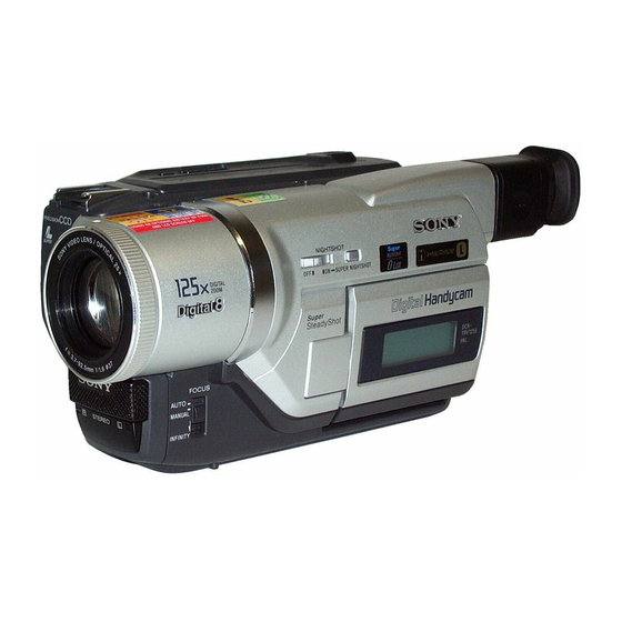
Photo: DCR-TRV320
SPECIFICATIONS
Viewfinder
Electric Viewfinder (monochrome)
Image device
1/4 type CCD (Change Coupled
Device)
DCR-TRV320/TRV320P/TRV520/
TRV520P/TRV525/TRV720 :
Approx. 460,000 pixels
(Effective: Approx. 290,000 pixels)
DCR-TRV320E/TRV420E/TRV520E/
TRV620E/TRV720E :
Approx. 800,000 pixels
(Effective: Approx. 400,000 pixels)
Lens
Combined power zoom lens
Filter diameter 37 mm (1 1/2 in.)
25× (Optical)
DCR-TRV320/TRV320E: E, AUS, HK,
CN/TRV320P/TRV420E: CN/TRV520/
TRV520E: E, AUS, HK, CN, JE/
TRV520P/TRV525/TRV720/TRV720E:
E, HK, CN :
450× (Digital)
DCR-TRV320E: AEP, UK, EE, NE, RU/
TRV520E: AEP/TRV620E/TRV720E:
AEP :
100× (Digital)
DCR-TRV420E: AEP :
125× (Digital)
DIGITAL VIDEO CASSETTE RECORDER
TRV620E/TRV720/TRV720E
DCR-TRV320E/TRV420E/TRV520E/TRV620E/TRV720E
For MECHANISM ADJUSTMENT, refer to
the "8mm Video MECHANICAL
ADJUSTMENT MANUAL
Focal length
3.7 - 92.5 mm (5/32 - 3 3/4 in.)
When converted to a 35 mm still camera
48 - 1200 mm (1 15/16 - 47 1/4 in.)
Colour temperature
Auto
Minimum illumination
DCR-TRV320/TRV320P/TRV520/
TRV520P/TRV525/TRV720 :
1 lux (F 1.6)
DCR-TRV320E/TRV420E/TRV520E/
TRV620E/TRV720E :
3 lux (F 1.6)
0 lux (in the NightShot mode)*
* Objects unable to be seen due to the
dark can be shot with infrared
lighting.
Input/output
connectors
DCR-TRV320/TRV320P/TRV520/
TRV520P/TRV525/TRV720 :
S video input/output
4-pin mini DIN
Luminance signal: 1 Vp-p,
75 ohms, unbalanced
Chrominance signal: 0.286 Vp-p,
75 ohms, unbalanced
RMT-814
US Model
DCR-TRV320/TRV520/TRV525/TRV720
Canadian Model
DCR-TRV320/TRV525/TRV720
AEP Model
UK Model
DCR-TRV320E/TRV620E
East European Model
North European Model
Russian Model
DCR-TRV320E
E Model
DCR-TRV320/TRV320E/TRV320P/
TRV520/TRV520E/TRV520P/TRV720/TRV720E
Hong Kong Model
DCR-TRV320/TRV320E/
TRV520/TRV520E/TRV720E
Korea Model
DCR-TRV320/TRV520/TRV720
Argentina Model
DCR-TRV520P
Australian Model
DCR-TRV320E/TRV520E
Chinese Model
DCR-TRV320E/TRV420E/TRV520E/TRV720E
Tourist Model
DCR-TRV520/TRV520E
" (9-973-801-11).
Audio/Video input/output
AV MINIJACK, 1 Vp-p, 75 ohms,
unbalanced, sync negative
327 mV, (at output impedance more than
47 kilohms)
Output impedance with less than 2.2
kilohms/Stereo minijack (ø 3.5 mm)
Input impedance more than 47 kilohms
DCR-TRV320E: E, AUS, HK, CN/
TRV420E: CN/TRV520E: E, AUS, HK,
CN, JE/TRV620E/TRV720E :
S video input/output
4-pin mini DIN
Luminance signal: 1 Vp-p,
75 ohms, unbalanced
Chrominance signal: 0.3 Vp-p,
75 ohms, unbalanced
Audio/Video output
AV MINIJACK, 1 Vp-p, 75 ohms,
unbalanced, sync negative
327 mV, (at output impedance more than
47 kilohms)
Output impedance with less than 2.2
kilohms/Stereo minijack (ø 3.5 mm)
DCR-TRV320E: AEP, UK, EE, NE, RU/
TRV420E: AEP/TRV520E: AEP :
– Continued on next page –
Advertisement
Chapters
Table of Contents

Related Manuals for Sony D8 Digital Handycam DCR-TRV520E


Summarization of Contents
SPECIFICATIONS
Lens
Details about the combined power zoom lens, including filter diameter and zoom magnification.
Input/output connectors
Details on various input/output connectors like S video, DV, and audio/video jacks.
SUPPLIED ACCESSORIES
Wireless Remote Commander
Details on the wireless remote commander accessory.
Battery pack
Information about the NP-F330 and NP-F550 battery packs supplied with the unit.
SAFETY CHECK-OUT
SAFETY-RELATED COMPONENT WARNING!!
Warning about critical safety components and the need for SONY replacement parts.
SERVICE NOTE
1. Power Supply During Repairs
Procedure to prevent power shut-off when supplying power during repairs.
2. To Take Out a Cassette When Not Eject (Force Eject)
Step-by-step instructions for forcefully ejecting a cassette.
4. Self-diagnosis Code Table
A table listing self-diagnosis codes, symptoms, and corrections for troubleshooting.
SELF-DIAGNOSIS FUNCTION
1. Self-diagnosis Function
Explanation of the self-diagnosis function and its display modes.
2. Self-diagnosis Display
Details on the 4-digit display indicating 'repaired by', 'block', and 'detailed code'.
3. Service Mode Display
How to access and interpret the service mode display showing up to six self-diagnosis codes.
SECTION 1 GENERAL
Quick Start Guide
Introduction to basic camcorder features and operations.
Recording a Picture
Basic instructions for recording a picture, including using auto focus and REC indicator.
Playing Back a Tape
Instructions on how to monitor playback pictures on the LCD screen or viewfinder.
Viewing the Recording on TV
Guidance on connecting the camcorder to a TV for viewing playback pictures.
Recording a Still Image on a Tape
Instructions on how to record still images on tape, including Tape Photo Recording.
Using the Fader Function
Explanation on how to use fader functions like M.FADER, BOUNCE, MONOTONE, OVERLAP, WIPE, DOT.
Using Special Effects
Details on digitally processing images for special effects like NEG. ART, SEPIA, B&W, SOLARIZE.
Using the PROGRAM AE Function
Explanation of various PROGRAM AE modes like Spotlight, Soft portrait, Sports lesson, Beach & ski.
Focusing Manually
Instructions on how to manually adjust focus for better results in challenging shooting conditions.
Making Your Own Titles
Guide to creating and storing custom titles with language, color, size, and position adjustments.
SECTION 2 DISASSEMBLY
2-1. 2.5 LCD ASSEMBLY, PD-117 BOARD
Detailed steps for disassembling the 2.5 LCD assembly and PD-117 board.
2-4. FRONT PANEL ASSEMBLY
Instructions for removing the front panel assembly.
2-6. CABINET (R) ASSEMBLY
Detailed steps for disassembling the cabinet (R) assembly.
2-16. LENS BLOCK
Instructions for disassembling the lens block.
2-20. CIRCUIT BOARDS LOCATION
Diagram showing the location of various circuit boards within the camcorder.
SECTION 3 BLOCK DIAGRAMS
3-1. OVERALL BLOCK DIAGRAM 1
An overview of the camcorder's internal circuitry and signal flow.
3-5. POWER BLOCK DIAGRAM 1
Detailed block diagram of the camcorder's power supply system.
SECTION 4 PRINTED WIRING BOARDS AND SCHEMATIC DIAGRAMS
4-1. FRAME SCHEMATIC DIAGRAMS
Schematic diagrams illustrating the overall frame of the camcorder's circuitry.
4-4. PARTS LOCATION
Diagrams indicating the physical location of various parts on the circuit boards.
SECTION 5 ADJUSTMENTS
1. Before Starting Adjustment
Preparation steps and list of required service tools before performing adjustments.
5-1. Camera Section Adjustment
Detailed procedures for adjusting the camera section, including HALL and flange back.
5-2. Mechanism Section Adjustment
Procedures for adjusting the mechanism section, tape path, and servo systems.
5-3. Video Section Adjustment
Adjustments related to video signals, including chroma BPF, S VIDEO OUT levels, and AFC.
5-4. SERVICE MODE
Information on accessing and using the service mode for various checks and data processing.
SECTION 6 REPAIR PARTS LIST
6-1. EXPLODED VIEWS
Diagrams showing the exploded views of major assemblies and their parts.
6-1-1. FRONT PANEL SECTION
Exploded view of the front panel assembly and its components.
6-1-2. CABINET (R) SECTION (2.5 LCD model)
Exploded view of the cabinet (R) section for 2.5 LCD models.
6-1-3. 2.5 LCD ASSEMBLY SECTION
Exploded view of the 2.5 LCD assembly.
6-1-4. CABINET (R) SECTION (3/3.5 LCD model)
Exploded view of the cabinet (R) section for 3/3.5 LCD models.
6-1-5. 3/3.5 LCD ASSEMBLY SECTION
Exploded view of the 3/3.5 LCD assembly.
6-1-6. CABINET (R) SECTION (4 LCD model)
Exploded view of the cabinet (R) section for 4 LCD models.
6-1-7. LCD EVF BLOCK SECTION
Exploded view of the LCD EVF block section.
6-1-8. CRT EVF BLOCK SECTION
Exploded view of the CRT EVF block section.
6-1-11. LENS BLOCK SECTION
Exploded view of the lens block assembly and its components.
6-1-12. MAIN BOARD SECTION
Exploded view of the main board section.
6-1-13. CASSETTE COMPARTMENT ASSEMBLY
Exploded view of the cassette compartment assembly.
6-1-14. LS CHASSIS ASSEMBLY
Exploded view of the LS chassis assembly.
6-1-15. MECHANISM CHASSIS ASSEMBLY
Exploded view of the mechanism chassis assembly.
6-2. ELECTRICAL PARTS LIST
A comprehensive list of electrical parts used in the camcorder.
Need help?
Do you have a question about the D8 Digital Handycam DCR-TRV520E and is the answer not in the manual?
Questions and answers