
Related Manuals for InoTec CPS 220/64/J-SV

Summary of Contents for InoTec CPS 220/64/J-SV
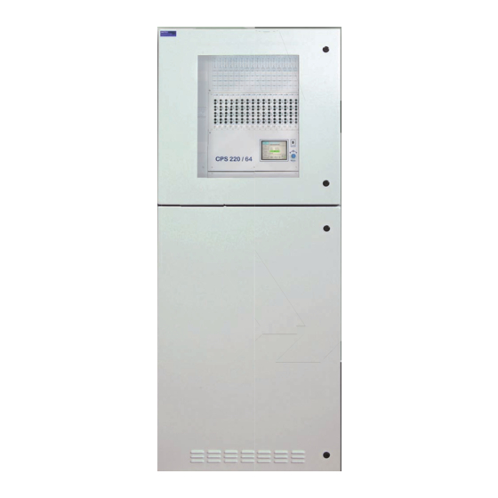
- Page 1 Mounting- and Operating Instructions Montage- und Betriebsanleitung Central Battery System Zentralbatteriesystem CPS 220 / 20 / J-SV / J-SKÜ CPS 220 / 20 / J-SV / J-SKÜ CPS 220 / 64 / J-SV / J-SKÜ CPS 220 / 64 / J-SV / J-SKÜ Sicherheitstechnik GmbH...
-
Page 3: Table Of Contents
CPS 220/64/SV Mounting and Operating Instructions CPS 220/64/SV Montage- und Betriebsanleitung Inhalt Contents 1. Allgemeine Hinweise 1. General information 1.1. Symbolerklärung 1.1. Explanation of symbols 1.2. Haftung und Gewährleistung 1.2. Liability and warranty 1.3. Ersatzteile 1.3. Spare parts 1.4. Entsorgung 1.4. - Page 4 CPS 220/64/SV Mounting and Operating Instructions CPS 220/64/SV Montage- und Betriebsanleitung 6.3.5. Zusätzliche Komponenten 6.3.5. Additional components 6.3.5.1. RIF 5 6.3.5.1. RIF 5 6.3.5.2. Batteriemanagementsystem BCS 43 6.3.5.2. Battery management system BCS 6.3.5.3. LSA 3 / LSA 8.1 6.3.5.3. LSA 3/LSA 8.1 6.3.5.4.
- Page 5 CPS 220/64/SV Mounting and Operating Instructions CPS 220/64/SV Montage- und Betriebsanleitung 9.4. Programmierung des CPS 220 Systems 9.4. Programming the CPS 220 system 9.4.1. Geräte- Programmierung 9.4.1. Device programming 9.4.2. Zielort 9.4.2. Destination 9.4.3. Platzbelegung 9.4.3. Position assignment 9.4.4. Stromkreisprogrammierung 9.4.4.
-
Page 6: Allgemeine Hinweise
Von INOTEC gelieferte Batterien und Elektronikbau- Batteries and electronic components supplied by teile können an INOTEC zurückgegeben werden INOTEC can be returned to INOTEC or should be oder sind gemäß den nationalen Richtlinien und disposed of in accordance with the national guide- Vorschriften für die Entsorgung von Alt-Batterien... -
Page 7: Sicherheitshinweise
Eventuelle Reparaturen oder Eingriffe dürfen involve opening the device must ONLY be carried out by ausschließlich durch INOTEC autorisierte Personen personnel authorised to do so by INOTEC. The guarantee vorgenommen werden. Eingriffe durch andere Personen becomes invalid if unauthorised personnel work on the führen zum Verlust der Gewährleistung. -
Page 8: Produktbeschreibung
CPS 220/64/SV Mounting and Operating Instructions CPS 220/64/SV Montage- und Betriebsanleitung 4. Produktbeschreibung 4. Product description Die Zentralbatteriesysteme CPS 220 / 20 und CPS 220 / 64 The central battery systems CPS 220/20 and CPS 220/64 sind ein batteriegestütztes Überwachungs- und Versor- are battery-supported monitoring and supply devices gungsgerät für den Notlichtbetrieb von Sicherheits- und for the emergency lighting operation of safety and emer-... - Page 9 CPS 220/64/SV Mounting and Operating Instructions CPS 220/64/SV Montage- und Betriebsanleitung direkt erfolgen als auch mittels optionaler PC-Software controller provides the option of saving text information und INOSTICK für Steuerteil mit vierzeiligem Display oder on change-over devices, modules and luminaires. The USB-Stick für TFT-Steuerteil.
-
Page 10: Aufbau Der Cps 220/20 Und Cps 220/64
CPS 220/64/SV Mounting and Operating Instructions CPS 220/64/SV Montage- und Betriebsanleitung • CPS 220 / 20 / 5,5kW / 3A, CPS 220 / 20 / 5,5kW / 7,5A • CPS 220/20/5.5 kW/3 A, CPS 220/20/5.5 kW/7.5 A Maximale Anschlussleistung 5,5kW mit 5 internen Maximum connected output 5.5 kW with 5 internal Modulplätzen für bis zu 20 Stromkreise und 16 externe module slots for up to 20 circuits and 16 external... - Page 11 CPS 220/64/SV Mounting and Operating Instructions CPS 220/64/SV Montage- und Betriebsanleitung CPS 220 / 64 / 11kW CPS 220 / 64 / 11kW-2 Netzanschluß Mains Klemmen /Anschlußraum Terminals Sicherungsabgänge US Netz/ Batt Substation output CP 4x2A CP 4x2A CP 4x2A CP 4x2A CP 4x2A CP 4x2A...
- Page 12 CPS 220/64/SV Mounting and Operating Instructions CPS 220/64/SV Montage- und Betriebsanleitung CPS 220 / 64 / 22kW- 3 phase Batteriesicherungen Battery fuses 850 008 850 009 Netzanschluß Mains CPS 220 / 64 / 11kW - 3 phase Anschlußklemmen Terminals CP 4x2A CP 4x2A CP 4x2A CP 4x2A...
-
Page 13: Cpusb 220
CPS 220/64/SV Mounting and Operating Instructions CPS 220/64/SV Montage- und Betriebsanleitung Netzanschluß CPUS 220 / 64 / 11kW Mains Klemmen Anschlußraum Terminals Sicherungsabgänge US Netz/ Batt Substation output Stromkreismodule Circuit modules CP 4x2A CP 4x2A CP 4x2A CP 4x2A CP 4x2A CP 4x2A CP 4x2A CP 4x2A... -
Page 14: Aufbau Der Cpusb - Systeme
= DL / M = DL / M = DL / M = DL / M = DL / M CPUSB 220 / 64 /1–2A CPUSB 220 / 64 /1–4A Klemmen Anschlußraum Terminals SK2 SK3 SK4 pot.frei Kontakte SL-SL+ Adresse INOTEC CPUSB 4x2A... -
Page 15: Cpusb 220 / 64 / 1-2X2,5A/24V
TFT-Steuerteil nutzbar. can only be used with a TFT controller. Rettungs- und Sicherheitsleuchten mit INOTEC 24V-Tech- Emergency exit and safety luminaires with INOTEC 24V nik und INOTEC 24V-D.E.R.-Leuchten für dynamische technology and INOTEC 24V-D.E.R. luminaires for dynamic Fluchtwegkennzeichnung können an die externe BUS-... -
Page 16: Cpusb 220 / 64 / 24V
CPUSB 220 / 64 / 24V Stromkreisklemmmen Anschlußraum Terminals Netz LSA1 LSA2 LSA3 LSA4 +24V Opt. Betr. +24V – – – Stoer Bat.-B. Steuerteil INOTEC Ein/On Ein/On Ein/On Ein/On Controller Betrieb Störung Störung Störung Störung Operation Failure Failure Failure Failure Batt.-Betrieb SK 1 SK 2... -
Page 17: Technische Daten
3,15 A 3,15 A 3,15 A 3,15 A 3,15 A 3,15 A 3,15 A 3,15 A INOTEC Betrieb Operation 9 10 11 12 13 14 15 16 17 18 19 20 Batt.-Betrieb 3,15 A 3,15 A 3,15 A 3,15 A... - Page 18 = DL / M = BL / NM = DL / M = BL / NM = DL / M = BL / NM = DL / M INOTEC Betrieb Batt.-Betrieb Störung La de- Störung Drucker Centronics CPS 220 / 64...
- Page 19 CP 4x2A CP 4x2A AIF CPS 220/20 3,15 A 3,15 A 3,15 A 3,15 A 3,15 A INOTEC Betrieb Operation 9 10 11 12 13 14 15 16 17 18 19 20 Batt.-Betrieb 3,15 A 3,15 A 3,15 A 3,15 A 3,15 A Batt.-Operat.
- Page 20 = BL / NM = DL / M = BL / NM = DL / M = BL / NM = DL / M INOTEC Betrieb Operation 9 10 11 12 13 14 15 16 17 18 19 20 Tiefe Batt.-Betrieb Batt.-Operat.
-
Page 21: Cpusb 220 / 64 / 1 - 4A
CPS 220/64/SV Mounting and Operating Instructions CPS 220/64/SV Montage- und Betriebsanleitung 5.2 CPUSB 220 / 64 / 16, 5.2 CPUSB 220/64/16, CPUSB 220/64/8–1, CPUSB 220 / 64 / 8 – 1, CPUSB 220/64/8–9 CPUSB 220 / 64 / 8 – 9, CPUSB 220/64/1–2A, CPUSB 220 / 64 / 1 - 2A, CPUSB 220/64/1–4 A... -
Page 22: Cpusb 220 / 64 / 24V
CPS 220/64/SV Mounting and Operating Instructions CPS 220/64/SV Montage- und Betriebsanleitung 5.3 CPUSB 220 / 64 / 24V 5.3 CPUSB 220/64/24 V Schutzklasse: Protection class: Schutzart: IP 20 Protection category: IP 20 Zulässige Umgebungstemperatur: Permissible ambient temperature: für das Gerät: -5°C bis +35°C For the device: -5°C to +35°C... -
Page 23: Aufstellung, Anschluss
CPS 220/64/SV Mounting and Operating Instructions CPS 220/64/SV Montage- und Betriebsanleitung 6. Aufstellung, Anschluss 6. Assembly, connection 6.1. Montage 6.1. Assembly Beachten Sie für die Lagerung der Komponenten For storage of the components through to assem- bis zur Montage die Hinweise in bly, observe the information in ... -
Page 24: Batterie
CPS 220/64/SV Mounting and Operating Instructions CPS 220/64/SV Montage- und Betriebsanleitung Jetzt kann die Haube des Gehäuses abgenommen wer- housing hood can now be removed. The six screws and den. Anschließend müssen die sechs Schrauben und die the front cover now have to be removed so that the hous- Frontabdeckung entfernt werden, um das Gehäuse an ing can be fastened to the wall. - Page 25 6.2.1. 1 battery cabinet with 1 battery set 18 blocks each 6.2.1. 1 Batterieschrank mit 1 Strang á 18 Blöcke Montage 12Ah Batterien 12Ah Batterie 12 Ah battery F1 F2 INOTEC 708 146 Sicherheitstechnik GmbH, 59 469 Ense...
-
Page 26: Batterieschränke Mit 1 Strang Á 18 Blöcke
CPS 220/64/SV Mounting and Operating Instructions CPS 220/64/SV Montage- und Betriebsanleitung 6.2.2. 2 Batterieschränke mit 1 Strang 6.2.2. 2 battery cabinets with 1 battery set á 18 Blöcke 18 blocks each F1 F2 6.2.3. 2 Batterieschränke mit 2 Strängen 6.2.3. 2 battery cabinets with 2 battery sets á... -
Page 27: Batteriemontage Auf Batteriegestell
Additional final circuits can be added to the CPS 220/64 Versorgungsleitung (L+ / N- / PE) Supply lead DPÜ gem. 0108 Batterieleitung (B+ / B-) INOTEC Battery cable CP 4x2A CP 4x2A CP 4x2A CP 4x2A CP 4x2A CP 4x2A... -
Page 28: Cpus 220 / 64
CPS 220/64/SV Mounting and Operating Instructions CPS 220/64/SV Montage- und Betriebsanleitung Unterstationen (CPUS 220 / 64 …) und BUS-Unterstatio- system using sub stations (CPUS 220/64 …) and BUS sub nen (CPUSB 220 / 64 …) um zusätzliche Endstromkreise stations (CPUSB 220/64 …). erweitert werden. - Page 29 = DL / M 6.3.2.6. Endstromkreise CP 24V-X7 6.3.2.6. Final circuits CP24V-X7 INOTEC 24V-LED-Leuchten werden an die Klemmen der Connect INOTEC 24V-LEDs to the terminals on terminal Klemmleiste X7 des jeweiligen Endstromkreises strip X7 of the respective final circuit. angeschlossen.
- Page 30 6.3.2.7 Final circuits CP D.E.R. - X14 CP D.E.R. 2x2,5A INOTEC 220V D.E.R. Leuchten werden an die Klemmen INOTEC 220V D.E.R. luminaries are connected to the ter- 3,15 AT 1500 L+, N-, B+, B- der Klemmleiste X14 angeschlossen. minals L+, N-, B+, B- on terminal rail X14.
- Page 31 Dieser Typ Stromkreisumschaltung kann in den CPS 220 / 20 and CPS 220 / 64 for INOTEC-emergency Anlagen CPS 220 / 20 und CPS 220 / 64 für INOTEC- lights in the 24Vor 24V D.E.R. versions. The circuit rack- Notleuchten mit 24V-Technik bzw. 24V D.E.R.-Technik mount unit also provides a corresponding safety extra- eingesetzt werden.
- Page 32 Die Stromkreisumschaltung CP D.E.R. 2x2,5A kann in den The change-over device CP D.E.R. 2x2,5A can be used Anlagen CPS 220/20 und CPS220/64 für INOTEC 220V in systems CPS 220/20 and CPS220/64 for INOTEC 220V D.E.R. Leuchten eingesetzt werden. D.E.R. luminaries.
-
Page 33: Cpusb 220 / 64 / 1
No output voltage spannung im in joker operation Jokerbetrieb Red (4 LEDs flashing Bus fault rot (blinken4 LEDs Busstörung quickly) INOTEC CPUSB 4x2A schnell) Red (4 LEDs flashing Current loop open INOTEC CPUSB 4x2A rot (blinken 4 LEDs Stromschleife slowly) langsam) geöffnet... - Page 34 CPS 220/64/SV Mounting and Operating Instructions CPS 220/64/SV Montage- und Betriebsanleitung Der maximale Einschaltstrom pro Stromkreis darf The maximum starting current per circuit may not nicht mehr als 250A für 500µs betragen! exceed 250A for 500 µs! Für die Stromkreisumschaltungen nur Orginalsi- Use only original fuses with extinguishing agents cherungen mit Löschmitteln verwenden.
- Page 35 • With DC operation via the CPS supply lead: Grundsätzliche Versorgung der Notleuchten aus der Basic supply to emergency luminaires via the CPS. CPS. INOTEC CPUSB 4x2A 6.3.3.6. Adressierung 6.3.3.6. Addressing Den BUS-Unterstationen CPUSB 220 / 64 / 1 - … muss...
-
Page 36: Cpusb 220 / 64 / 24V
– – – Stoer Bat.-B. Die Verkabelung erfolgt über die oberen Cables are inserted from above. Kabeleinführungen. INOTEC Ein/On Ein/On Ein/On Ein/On In the housing for surface-mounting the CPUSB Im Aufputzgehäuse der CPUSB 2220 / 64 / 24V ist Betrieb 2220/64/24 V, cables can also be inserted from auch eine rückseitige Kabeleinführung möglich. - Page 37 Im Fall der Nachinstallation ist darauf zu achten, dass jede to ensure that each luminaire ID for each circuit is con- Leuchten-ID pro Stromkreis nur einmal an der CLS ange- nected to the CLS only once! schlossen wird! INOTEC 860 02 1 L-JET Leuchten-ID 56 381 ta: 50°C/U n :DC 24V±20%...
- Page 38 Öffner der DPÜ DPÜ DPÜ gem. gem. gem. 0108 0108 0108 NC-contact of Dreiphasen- INOTEC INOTEC INOTEC the three-phase überwachung UVA 1 UVA 2 UVA 3 sub db 1 sub db 2 sub db 3 monitor. Should anzuschließen.
-
Page 39: Zusätzliche Komponenten
CPS 220/64/SV Mounting and Operating Instructions CPS 220/64/SV Montage- und Betriebsanleitung 6.3.4.6. Zentrales Dimmen 6.3.4.6. Central dimming Mit dem optionalen CLS- The optional CLS dimmer module oder Dimmer Modul können ent- allows programmed luminaires Potenziometer sprechend programmierte in the circuits to be dimmed cen- 0-10V Leuchten in den Stromkrei- trally via... - Page 40 For temperature controlled charging, a temperature turfühler (Typ KTY oder INOTEC Sensor) innerhalb des sensor (type KTY or INOTEC sensor) must be connected Batterieraums an die Klemmen T+ / T- des RIF 5-Moduls inside the battery compartment to terminals T+/T- of the anzuschließen.
-
Page 41: Siehe 8.4.2.3.2. Steuerteilprogrammierung
General lighting General lighting DPÜ DPÜ DPÜ gem. gem. gem. 0108 0108 0108 INOTEC INOTEC INOTEC UVA 1 UVA 2 UVA 3 Anschlüsse bei Überwachung ein- und dreiphasiger Netze Supply monitoring in single- and three-phase installation. SL- SL+ 850 009 RIF5 Der Fernschaltkreis sowie die 24V-Stromschleife können... -
Page 42: Siehe 9.4.6. Module
DPÜ / B.1 DPÜ / B.1 DPÜ / B.1 890 414 890 414 890 414 INOTEC INOTEC INOTEC Kontakte (1 / 2) + (3 / 4) Kontakte (1 / 2) + (3 / 4) Kontakte (1 / 2) + (3 / 4) Letzte DPÜ... -
Page 43: Batteriemanagementsystem Bcs
CPS 220/64/SV Mounting and Operating Instructions CPS 220/64/SV Montage- und Betriebsanleitung 6.3.5.2. Batteriemanagementsystem BCS 6.3.5.2. Battery management system BCS Das Batteriemanagementsystem BCS ist nur mit The battery management system BCS can only be TFT-Steuerteil nutzbar. used with a TFT controller. Das Batteriemanagementsystem BCS besteht aus The battery management system consists of one control einer Kontrolleinheit und max. - Page 44 CPS 220/64/SV Mounting and Operating Instructions CPS 220/64/SV Montage- und Betriebsanleitung Zustand Zustand Reaktion Emerg. light device BCS sensor Reaction Notlichtgerät BCS-Sensor state state AC-Betrieb Unterspannung Ladung wird AC operation and Undervoltage Charging is und Ladung ausgeschaltet charging switched on switched off eingeschaltet Überspannung...
- Page 45 CPS 220/64/SV Mounting and Operating Instructions CPS 220/64/SV Montage- und Betriebsanleitung Durch drücken der unteren Taste (Enter-Taste ) erscheint Pressing the lower button (Enter button) calls up the das Menü des BCS-Moduls. Mittels der Pfeiltasten kann menu of the BCS module. The arrow buttons can be used durch das Menü...
- Page 46 CPS 220/64/SV Mounting and Operating Instructions CPS 220/64/SV Montage- und Betriebsanleitung...
-
Page 47: Lsa 3 / Lsa
CPS 220/64/SV Mounting and Operating Instructions CPS 220/64/SV Montage- und Betriebsanleitung 6.3.5.3. LSA 3 / LSA 8.1 6.3.5.3. LSA 3/LSA 8.1 Mit den LSA 8.1- und LSA 3-Modulen ist ein gemeinsames With the LSA 8.1 and LSA 3 modules, the main and safety Ein- und Ausschalten von Netz- und Sicherheitsleuchten luminaires can be switched on and off together. - Page 48 CPS 220/64/SV Mounting and Operating Instructions CPS 220/64/SV Montage- und Betriebsanleitung 6.3.5.3.2. LSA 8.1 6.3.5.3.2. LSA 8.1 Pro Steuerteil sind bis zu 3 LSA 8.1-Module an den Gerä- Up to 3 LSA 8.1 modules can be connected to the device tebus anschließbar.
-
Page 49: See 9.4.6. Modules
Accordingly, the unoccupied contacts must be sup- chend mit Spannung am Eingang zu versorgen! plied with power at the input! UV 1 UV 2 DPÜ DPÜ gem. gem. 0108 0108 INOTEC INOTEC 24V– 24V– 24V– 24V– 24V– 24V– 24V– 24V– 850 007... -
Page 50: Dreiphasenüberwachungen
CPS 220/64/SV Mounting and Operating Instructions CPS 220/64/SV Montage- und Betriebsanleitung LSA 8.1 230V LSA 8.1 230 V Technische Daten: Technical data: Nennspannung Rated voltage of 71,5 Abfrageeingänge: 230 V AC the polling inputs: 230 V AC Temp.-Bereich: -15°C ... +40°C Amb. -
Page 51: Mm² Single-Wire Or
CPS 220/64/SV Mounting and Operating Instructions CPS 220/64/SV Montage- und Betriebsanleitung Technische Daten: Technical data: Nennspannung U 230 V AC, 400 V AC Rated voltage U 230 V AC, 400 V AC Überlastbarkeit: Overload capacity 1,1 U dauernd 1.1 U continuous Nennverbrauch: ca. - Page 52 50/60 Hz Rated frequency: 50/60 Hz Ansprechwert: 0,85 U Response value: 0.85 U Busanschluss: INOTEC interner Gerätebus Bus connection: INOTEC internal device bus Adressbereich: 1 . . . 31 Address range: 1–31 Ausgang Output Kontaktbestückung: 2 Schließer Contacts 2 NO-contacts...
-
Page 53: Lomo
Zener diode Zener diode DPÜ DPÜ DPÜ DPÜ DPÜ DPÜ DPÜ DPÜ DPÜ SL - SL - SL - INOTEC INOTEC INOTEC 850 009 850 009 LOMO LOMO LOMO 850 014 850 014 850 014 24 V. 24 V. 24 V. -
Page 54: Fernmeldetableau - Mtb
CPS 220/64/SV Mounting and Operating Instructions CPS 220/64/SV Montage- und Betriebsanleitung 6.3.5.6. Fernmeldetableau – MTB 6.3.5.6. Remote mimic panel — MTB Das Fernmeldetableau wird an das RIF5-Modul gem. The remote mimic panel is connected to the RIF5 module nachfolgendem Schaltbild angeschlossen. Die Leitungs- in accordance with the circuit diagram below. -
Page 55: Cps-Mtb
= DL / M = DL / M = DL / M = DL / M = DL / M = DL / M = DL / M Max. Leitungslänge Störung INOTEC INOTEC INOTEC Failure Betrieb Betrieb Betrieb Batt.-Betrieb Batt.-Betrieb Batt.-Betrieb... -
Page 56: Inoweb
CPS 220/64/SV Mounting and Operating Instructions CPS 220/64/SV Montage- und Betriebsanleitung 6.3.5.8. INOWEB 6.3.5.8. INOWEB Über das im Kompfortsteuerteil (TFT) integriert INOWEB- The INOWEB (integrated in TFT comfort controller unit) Modul kann der Zustand des CPS-Gerätes mittels Netz- module enables the status of the CPS device to be polled werkverbindung abgefragt werden. -
Page 57: Inbetriebnahme
System wieder eingeschaltet werden. the insulation measuring is complete. Die Isolationsmessung nicht an Stromkreisen mit Do not perform the insulation measurement on INOTEC 24V-Leuchten durchführen. Die Leuchten the circuits with INOTEC 24V luminaires. This would werden zerstört. destroy the luminaires. -
Page 58: Ausschalten Des Zentralbatteriesystems
CPS 220/64/SV Mounting and Operating Instructions CPS 220/64/SV Montage- und Betriebsanleitung Die Isolationsmessung ist mit einer max. Messspannung The insulation must be measured with a max. measure- von 500V DC und einem Messstrom von 1mA durchzufüh- ment voltage of 500 V DC and a measurement current ren! Es dürfen nur Messgeräte verwendet werden, die den of 1mA! Only measuring devices that satisfy the require- Anforderungen der DIN VDE 0413 genügen. -
Page 59: Programmierung Des Cps 220-Systems Mit Standardsteuerteil
8. Programmierung des CPS 8. Programming the CPS 220 system 220-Systems mit Standardsteuerteil with standard controller 8.1. Allgemeines 8.1. General INOTEC Betrieb 9 10 11 12 13 14 15 16 17 18 19 20 Operation C P S Batt.-Betrieb B e t r ie b Batt.-Operat. -
Page 60: Testmenü
CPS 220/64/SV Mounting and Operating Instructions CPS 220/64/SV Montage- und Betriebsanleitung 8.2. Testmenü 8.2. Test menu 8.2.1. Funktionstest starten 8.2.1. Running a function test Menü Testauslösung FT/BT/Learn Menu Test menu FT/DT/Learn Start FT ... -
Page 61: Tiefentladeschutz Prüfen
CPS 220/64/SV Mounting and Operating Instructions CPS 220/64/SV Montage- und Betriebsanleitung um die Stromaufnahme der angeschlossenen Verbrau- sumption of the connected consumers. This function can cher zu ermitteln. Diese Funktion kann ebenfalls für also be activated for the entire central battery device (sys- das ganze Zentralbatteriegerät (System) oder für einen tem) or for one circuit. -
Page 62: Betriebsdauertest Abbrechen
CPS 220/64/SV Mounting and Operating Instructions CPS 220/64/SV Montage- und Betriebsanleitung 8.2.7. Betriebsdauertest abbrechen 8.2.7. Cancelling battery duration test BT-Abbruch Cancel DT Ein versehentlich gestarteter Betriebsdauertest kann im A battery duration test that has been started accidentally Hauptmenü über den Befehl „BT-Abbruch“ nach ca. 5 can be stopped manually in the main menu using the Sekunden manuell beendet werden. - Page 63 CPS 220/64/SV Mounting and Operating Instructions CPS 220/64/SV Montage- und Betriebsanleitung weiter zum Durchblättern der Informationen des Next to scroll through the information on the gewählten Platzes selected slot Unter anderem sind folgende Informationen abrufbar: The retrievable information includes: •...
-
Page 64: Störungs Info
CPS 220/64/SV Mounting and Operating Instructions CPS 220/64/SV Montage- und Betriebsanleitung • SLÜ mit / ohne SL- Schleifenüberwachung • SLÜ with/without SL monitoring loop function (module) • SLÜ mit / ohne FS- Schleifenüberwachung • SLÜ with/without RS monitoring loop function (module) •... -
Page 65: Prüfbuch
CPS 220/64/SV Mounting and Operating Instructions CPS 220/64/SV Montage- und Betriebsanleitung 8.3.3. Prüfbuch 8.3.3. Logbook Menü Info Prüfbuch Menu Info Logbook Im Prüfbuch werden Statusänderungen des Zentral- Status changes of the central battery device and the batteriegerätes und die Ergebnisse von Funktions- und results of function and battery duration tests are saved to Betriebsdauertest gespeichert. -
Page 66: Programmierung
CPS 220/64/SV Mounting and Operating Instructions CPS 220/64/SV Montage- und Betriebsanleitung Es können alle Einträge ausgedruckt werden oder die All entries or the most recent entries can be printed aktuellsten Einträge (max. die 255 neusten Einträge). Der (max. 255 most recent entries). Printing is cancelled Ausdruck wird mit „Drucken abbrechen „... -
Page 67: Programmierung
CPS 220/64/SV Mounting and Operating Instructions CPS 220/64/SV Montage- und Betriebsanleitung 8.4.2. Programmierung 8.4.2. Programming Um die Einstellungen vor unbefugtem Zugriff zu schüt- To protect the settings from unauthorised access, a pass- zen, ist eine Passwortabfrage eingebaut. Das Passwort word prompt is integrated. The password can be individu- kann in den Geräteeinstellungen individuell gewählt wer- ally selected in the device settings. - Page 68 CPS 220/64/SV Mounting and Operating Instructions CPS 220/64/SV Montage- und Betriebsanleitung 8.4.2.2. INOSTICK 8.4.2.2. INOSTICK Menü Programmierung Programmierung Menu Programming Programming INOSTICK INOSTICK K o n f i g v o m I N O S T I C K I N O S T I C K...
- Page 69 CPS 220/64/SV Mounting and Operating Instructions CPS 220/64/SV Montage- und Betriebsanleitung 8.4.2.3. Programmierung 8.4.2.3. Programming Menü Programmierung Programmierung Menu Programming Programming Programmierung Programming Die Programmierung im Steuerteil kann vor unbefugtem The programming in the controller can be protected Zugriff mit einem 4-stelligem Passwort geschützt werden.
- Page 70 CPS 220/64/SV Mounting and Operating Instructions CPS 220/64/SV Montage- und Betriebsanleitung Es können bis zu drei LSA 8-Module am Gerät Up to three LSA 8 modules can be registered on angemeldet werden, welche entweder am BUS IB 1 the device. These are connected either to BUS IB1 (interne Gerätekomponenten) oder BUS IB2 (externe (internal device components) or BUS IB2 (external Gerätekomponenten) angeschlossen sind.
- Page 71 CPS 220/64/SV Mounting and Operating Instructions CPS 220/64/SV Montage- und Betriebsanleitung Folgende Meldungen stehen zur Auswahl: The following messages are available: • Ladestörung ja/nein • Charging failure Yes/no • Stromkreisstörung ja/nein • Circuit failure Yes/no • Netzausfall HV ja/nein • Main-db failure Yes/no •...
- Page 72 CPS 220/64/SV Mounting and Operating Instructions CPS 220/64/SV Montage- und Betriebsanleitung PC-Tastatur mit PS/2-Anschluss benötigt. the destinations. F 4 < > F 5 D P Ü / B : F 4 < > F 5 D P Ü / B : U n t e r v e r t e i l .
- Page 73 CPS 220/64/SV Mounting and Operating Instructions CPS 220/64/SV Montage- und Betriebsanleitung Die Festlegung welche Betriebsarten blockiert wurden, The modes that have been blocked are specified in the geschieht im Menü „Funktion Fernschalter blockiert“: menu "Remote switch function blocked" menu: • Dauerlicht (DL) •...
- Page 74 CPS 220/64/SV Mounting and Operating Instructions CPS 220/64/SV Montage- und Betriebsanleitung Ausdruck der Anlagenkonfiguration Configuration printout Die Konfiguration des Gerätes kann über einen The device configuration can be printed out via angeschlossenen Drucker oder mittels INOPRINT a connected printer or using INOPRINT. ausgedruckt werden.
- Page 75 CPS 220/64/SV Mounting and Operating Instructions CPS 220/64/SV Montage- und Betriebsanleitung Zuordnung von Schalteingängen Assignment of input switches In den Schaltungsarten „Dauerlichtstromkreis geschaltet“ In operation modes "Maintained lighting circuit con- und „Joker Stromkreis geschaltet“ können jedem Strom- nected" and "Joker circuit connected", up to three input kreis bis zu drei Schalteingänge (LSA 8, LSA 3, DPÜ/B) switches (LSA 8, LSA 3, DPÜ/B) can be assigned to each zugeordnet werden.
- Page 76 CPS 220/64/SV Mounting and Operating Instructions CPS 220/64/SV Montage- und Betriebsanleitung Einzelleuchtenüberwachung Individual luminaire monitoring Ist die Überwachungsart „Einzelleuchtenüberwachung“ If "Individual luminaire monitoring" is selected, up to 20 ausgewählt, so können bis zu 20 Leuchten angemeldet luminaires can be registered. You must state whether or werden.
-
Page 77: Programmierung Des Cps 220 - Systems Mit Komfortsteuerteils
CPS 220/64/SV Mounting and Operating Instructions CPS 220/64/SV Montage- und Betriebsanleitung 9. Programmierung des CPS 220 - 9. Programming the CPS 220 system Systems mit Komfortsteuerteils with comfort controller 9.1. Allgemeines 9.1. General Das Steuerteil der CPS 220 besteht aus einem TFT Bild- The CPS 220 controller comprises a TFT screen, a control schirm, einem Bedienknopf und einem USB Anschluss. -
Page 78: Aktualisierung Der Sd- Karte
CPS 220/64/SV Mounting and Operating Instructions CPS 220/64/SV Montage- und Betriebsanleitung 9.1.1. Aktualisierung der SD- Karte 9.1.1. Updating the SD card Um die Gerätekonfi guration dauerhaft zu spei- To save the device confi guration permanently, it chern, ist es nach einigen Schritten notwendig has to be saved to the SD card after a few steps. -
Page 79: Funktionstest Starten / Abbrechen
CPS 220/64/SV Mounting and Operating Instructions CPS 220/64/SV Montage- und Betriebsanleitung 9.2. Funktionstest starten / abbrechen 9.2. Running/ cancelling a function test FT starten: Start FT: FT markieren auswählen FT Mark Select FT starten markieren auswählen ... -
Page 80: Geräte Info
CPS 220/64/SV Mounting and Operating Instructions CPS 220/64/SV Montage- und Betriebsanleitung Folgende Punkte sind im Info- Menü auswählbar: The following options can be selected from the Info • Geräte- Info menu: • Prüfbuch • Device info • Störungsausdruck • Logbook •... -
Page 81: Prüfbuch
CPS 220/64/SV Mounting and Operating Instructions CPS 220/64/SV Montage- und Betriebsanleitung 9.3.2. Prüfbuch 9.3.2. Logbook Info markieren auswählen Info Mark Select Prüfbuch markieren auswählen Logbook Mark Select Im Prüfbuch der Anlage werden alle Ereignisse, wie All events such as status changes and test results are Zustandsänderungen und Testergebnisse gespeichert. -
Page 82: Stromkreisinformationen
CPS 220/64/SV Mounting and Operating Instructions CPS 220/64/SV Montage- und Betriebsanleitung 9.3.4. Stromkreisinformationen 9.3.4. Circuit info Durch die Auswahl einer Stromkreisumschaltung im Info- Selecting a change-over device in the Info menu allows Menü lassen sich Informationen der gesamten Strom- you to display information about the change-over device kreisumschaltung, sowie detaillierte Informationen zu as a whole and detailed information on each individual jedem einzelnen Stromkreis des ausgewählten Einschubs... - Page 83 CPS 220/64/SV Mounting and Operating Instructions CPS 220/64/SV Montage- und Betriebsanleitung • Überwachungsart • Monitoring option • Stromkreisüberwachung: • Circuit monitoring: Toleranz für die Stromwertabweichung in %, Soll- / Tolerance for the current value deviation in %, Ist- Stromwert target/actual current value •...
-
Page 84: Batterie- Info
CPS 220/64/SV Mounting and Operating Instructions CPS 220/64/SV Montage- und Betriebsanleitung 9.3.5. Batterie- Info 9.3.5. Battery info Das Menü Batterie-Info wird folgendermaßen aufgerufen: The Battery info menu is accessed as follows: Info markieren auswählen Info Mark Select Batterie markieren auswählen ... -
Page 85: Dpü- Info
CPS 220/64/SV Mounting and Operating Instructions CPS 220/64/SV Montage- und Betriebsanleitung 9.3.6. DPÜ- Info 9.3.6. DPÜ info Im Menü DPÜ- Info werden alle angemeldeten DPÜ/B- The DPÜ info menu displays all registered DPÜ/B mod- Module und deren Status angezeigt. ules and their statuses. ... - Page 86 CPS 220/64/SV Mounting and Operating Instructions CPS 220/64/SV Montage- und Betriebsanleitung • LSA8 • LSA8 • LSA3 • LSA3 • RIF • RIF • SHUNT • SHUNT • SLÜ • SLÜ Durch Drehen markieren und Drücken auswählen Turning Mark and pushing Select displays detailed werden Detailinformationen zu diesen Komponenten information on these components.
- Page 87 CPS 220/64/SV Mounting and Operating Instructions CPS 220/64/SV Montage- und Betriebsanleitung In diesem Untermenü werden folgende Detailinformati- This sub-menu displays the following detailed onen zum SLÜ- Modul (separates Modul oder integriert information on the SLÜ module (separate module im RIF5- Modul) angezeigt: or integrated into the RIF5 module): •...
- Page 88 CPS 220/64/SV Mounting and Operating Instructions CPS 220/64/SV Montage- und Betriebsanleitung Detaillierte Status- Informationen der LSA8.1-, sowie Detailed status information on the LSA8.1 and the LSA3 LSA3- Module werden im Menü LSA8- / LSA3- Info module is displayed in the LSA8/LSA3 info menu. Select angezeigt.
- Page 89 CPS 220/64/SV Mounting and Operating Instructions CPS 220/64/SV Montage- und Betriebsanleitung 9.4.1. Geräte- Programmierung 9.4.1. Device programming Gerätetyp Device type Das Steuerteil kann entweder als „Gerät“ programmiert The controller can be programmed either as a "device" — werden – dann werden auch angeschlossene Ladeteile in which case connected chargers will also be controlled mit angesteuert –...
- Page 90 CPS 220/64/SV Mounting and Operating Instructions CPS 220/64/SV Montage- und Betriebsanleitung Password entry Passworteingabe The programming can be protected from unauthorised Die Programmierung kann mit einem vier-stelligen access with a four-digit code. Zahlencode vor unbefugtem Zugriff geschützt werden. The password can be entered either via the USB keyboard Eine Eingabe des Passwortes kann sowohl über or by "soft key"...
- Page 91 CPS 220/64/SV Mounting and Operating Instructions CPS 220/64/SV Montage- und Betriebsanleitung 9.4.2. Zielort 9.4.2. Destination Die Zielorte der Stromkreiseinschübe werden über den The destinations of the circuit change-over devices are Menüpunkt „Zielorte“ eingegeben. Nach Auswahl des entered via the "Destinations" menu option. Once the entsprechenden Einschubs wird mittels der USB-Tastatur required change-over device has been selected, its desti- der Zielort des Stromkreiseinschubs erfasst.
- Page 92 CPS 220/64/SV Mounting and Operating Instructions CPS 220/64/SV Montage- und Betriebsanleitung 9.4.4. Stromkreisprogrammierung 9.4.4. Circuit programming Programmierung markieren auswählen Programming Mark Select gewünschten Einschub markieren Required change-over device Mark Select auswählen Zielorteingabe Stromkreis Entering the circuit destination Nach auswählen des entsprechenden Stromkreises After selection of the required circuit, the destination kann der Zielort mit der USB-Tastatur für den Stromkreis...
- Page 93 CPS 220/64/SV Mounting and Operating Instructions CPS 220/64/SV Montage- und Betriebsanleitung Bei Endstromkreisen mit Stromkreisüberwachung In the case of final circuits with circuit monitoring, ist anschließend der Learn-Mode für SKÜ-Strom- learn mode for SKÜ circuits must then be run to kreise durchzuführen, um die Stromwerte der determine the current values for the connected ...
- Page 94 24V-Leuchte In contrast to the circuit change-over devices with 230 V, Im Unterschied zu den Stromkreiseinschüben mit 230V ist the switching mode of every 24V-INOTEC luminaire must die Schaltungsart jeder 24V-INOTEC-Leuchte vom Steuer- be programmed from the controller. teil aus zu programmieren.
- Page 95 CPS 220/64/SV Mounting and Operating Instructions CPS 220/64/SV Montage- und Betriebsanleitung 24V-D.E.R.-Leuchte 24V-D.E.R.-luminaire If „DER 24V“ luminaire is set via „Change“ Selected, the Wird als Belegung eine „DER 24V“-Leuchte mittels „Aen- dern“ ausgewählt, ist für diese auch die Adresse der address of the light must also be entered under „Ind.
- Page 96 CPS 220/64/SV Mounting and Operating Instructions CPS 220/64/SV Montage- und Betriebsanleitung < Pfeil links < Arrow left > Pfeil rechts > Arrow right Pfeil unten Arrow down Fluchtweg gesperrt (rotes Kreuz) Escape route blocked (red X) Blinken (Flash) Flash Piktogramm an Pictogram on Mehrere Darstellungen können miteinander verknüpft Multiple displays can be linked together.
- Page 97 CPS 220/64/SV Mounting and Operating Instructions CPS 220/64/SV Montage- und Betriebsanleitung LSA 8 – Module LSA 8 modules Programmierung markieren auswählen Programming Mark Select Komponenten markieren auswählen Components Mark Select LSA8 markieren auswählen LSA8 Mark Select Es können bis zu drei LSA 8-Module am Gerät ange- Up to three LSA 8 modules can be registered on the meldet werden, welche entweder am BUS IB 1 (interne...
- Page 98 CPS 220/64/SV Mounting and Operating Instructions CPS 220/64/SV Montage- und Betriebsanleitung Für jeden Eingangskanal ist es möglich, mittels einer For each input channel, a destination designation can be USB-Tastatur, eine Zielortbezeichnung zu hinterlegen. defined using a USB keyboard. Die Module können nur am IB 2 betrieben werden! The modules can be operated only on the IB2.
- Page 99 CPS 220/64/SV Mounting and Operating Instructions CPS 220/64/SV Montage- und Betriebsanleitung SHUNT SHUNT Programmierung markieren auswählen Programming Mark Select Komponenten markieren auswählen Components Mark Select SHUNT markieren auswählen SHUNT Mark Select Dieser Menüpunkt ist nur verfügbar, wenn als Funktion in This menu option is available only if "Device"...
- Page 100 CPS 220/64/SV Mounting and Operating Instructions CPS 220/64/SV Montage- und Betriebsanleitung 9.5. Testmenü 9.5. Test menu Test Menü markieren auswählen Test Menu Mark Select Im Testmenü werden die Einstellungen zum automati- The test menu displays the settings for the automatic schen Funktionstest und Betriebsdauertest angezeigt, function test and battery duration test, as well as the sowie die Dauer des letzten Betriebsdauertests.
- Page 101 CPS 220/64/SV Mounting and Operating Instructions CPS 220/64/SV Montage- und Betriebsanleitung Die angeschlossenen Verbraucher müssen zum At the time the learn mode is executed, the con- Zeitpunkt des Learnmodes in funktionstüchtigem nected consumers must be functional. The age of Zustand sein. Alter der Leuchtmittel, Temperatur, the illuminant, temperature, etc.
- Page 102 CPS 220/64/SV Mounting and Operating Instructions CPS 220/64/SV Montage- und Betriebsanleitung 9.6. Einstellungen 9.6. Settings Einstellung markieren auswählen Setting Mark Select Folgende Einstellungen zum Steuerteil stehen in diesem The following settings for the controller are available Menü zur Verfügung: from this menu: •...
- Page 103 CPS 220/64/SV Mounting and Operating Instructions CPS 220/64/SV Montage- und Betriebsanleitung 9.6.2.1. Manuelles Zeitupdate 9.6.2.1. Manual time update Hours, minutes, days, months and years can be marked Die Stunden, Minuten, Tage, Monate und Jahre können nach dem markieren durch auswählen eingestellt and then set with Select.
- Page 104 The configuration is saved in the CONF_WR directory on USB-Speichermedium gespeichert und kann mit der the USB storage medium and can be edited and printed optionalen INOTEC Konfiguratorsoftware bearbeitet und out using the optional INOTEC configurator software. ausgedruckt werden. 9.6.3.2. USB > Konfig 9.6.3.2. USB > config ...
- Page 105 CPS 220/64/SV Mounting and Operating Instructions CPS 220/64/SV Montage- und Betriebsanleitung 9.6.3.4. PB > USB 9.6.3.4. Logbook > USB Einstellung markieren auswählen Setting Mark Select USB markieren auswählen USB Mark Select Logbook > USB Mark Select ...
- Page 106 CPS 220/64/SV Mounting and Operating Instructions CPS 220/64/SV Montage- und Betriebsanleitung Bei TFT-Steuerteilversion kleiner als 1.2.15 sind die the files for the software update must be copied to the Dateien für das Softwareupdate in das Verzeichnis "Update_cps220" directory. For version 1.2.15 or higher, „Update_cps220“...
- Page 107 CPS 220/64/SV Mounting and Operating Instructions CPS 220/64/SV Montage- und Betriebsanleitung 9.7. INOWEB 9.7. INOWEB Über die INOWEB-Schnittstelle können die Statusinforma- The status information on the luminaire can be displayed tionen zur Leuchte mittels eines Webbrowser dargestellt via the INOWEB interface using a web browser. To that werden.
- Page 108 CPS 220/64/SV Mounting and Operating Instructions CPS 220/64/SV Montage- und Betriebsanleitung The destinations are shown in the current display, which Die Zielorte werden in der Stromkreisdarstellung ange- can be shown by clicking the luminaires. zeigt, die mit einem Mausklick auf die Leuchten aufgeru- fen wird.
- Page 109 Für die Stromkreise am IB 2 ist folgende Adresse http://<IP-Adresse_TFT-Steuerteil>/cgi-bin/ einzugeben: cgi_inoweb?text=X_2 http://<IP-Adresse_TFT-Steuerteil>/cgi-bin/ cgi_inoweb?text=X_2 Externer Link des Gerätes http://www.inotec-licht.de Externer Link des Gerätes http://www.inotec-licht.de Ext. Link Platz 01: Stromkreis 01 http://www.inotec-licht.de/erdgeschoss.pdf Ext. Link Platz 01: circuit 01 http://www.inotec-licht.de/erdgeschoss.pdf Ext. Link Platz 01: Stromkreis 02 http://www.google.de...
- Page 110 CPS 220/64/SV Mounting and Operating Instructions CPS 220/64/SV Montage- und Betriebsanleitung A green check mark next to the Apache indicates that the Ein grüner Haken neben dem Feld Apache deutet an, dass server was started. der Webserver gestartet wurde. Starting behaviour and the TCP-port can be configured Unter „Settings“...
- Page 111 CPS 220/64/SV Mounting and Operating Instructions CPS 220/64/SV Montage- und Betriebsanleitung 10. Programmierung CPUSB 220/64/24 10. Programming CPUSB 220/64/24 10.1. Bedienung und Menüstruktur 10.1. Operation and menu structure INOTEC INOTEC C P U S B 2 4 V...
- Page 112 Werkseitig ist „0000“ als Passwort eingestellt. password is "0000". 10.3.1. Geräteeinstellungen 10.3.1. Program device INOTEC INOTEC OK Programmierung OK Geräteprog. OK OK Programming OK Device prog. OK U n t e r s t a t i o n...
- Page 113 Opt. Relay" menu. It is also possible to select several mes- auch mehrere Meldungen auszuwählen, die dann mit sages, which are then associated with "OR". INOTEC „Oder“ verknüpft werden. INOTEC N e t z a u s f a l l...
- Page 114 CPS 220/64/SV Mounting and Operating Instructions CPS 220/64/SV Montage- und Betriebsanleitung INOTEC INOTEC S t r o m k r e i s : C i c u i t : Z u m u n d a b m e l d e n p r e s s d r ü...
- Page 115 Lichtschalterabfrage zu schal- switches in the light sequence switching within the sys- ten. Es können dabei zwei Zuordnungen pro Leuchte tem. Two switches can be assigned to each luminaire. INOTEC INOTEC getroffen werden. L e u c h t e : S K : 1 L u m .
- Page 116 CPS 220/64/SV Montage- und Betriebsanleitung 10.3.5. Passwort ändern 10.3.5. Change password OK Programmierung OK Passwort ändern OK Programming OK Change password INOTEC INOTEC G e b e n S i e e i n e...
- Page 117 CPS 220/64/SV Mounting and Operating Instructions CPS 220/64/SV Montage- und Betriebsanleitung 10.5 Block. Aufheben 10.5 Device block Ein blockiertes CPUSB-Gerät wird über diesen Befehl A blocked CPUSB device is re-activated via this command wieder freigegeben, sobald ein Haken signalisiert, dass es as soon as a tick signals that the block can be cancelled.
- Page 118 CPS 220/64/SV Mounting and Operating Instructions CPS 220/64/SV Montage- und Betriebsanleitung 11.2.2 Wöchentliche Prüfung 11.2.2 Weekly test Eine wöchentliche Umschaltung auf die Stromquelle für A changeover to the power source must be carried out Sicherheitszwecke hat zu erfolgen und die Funktion der every week for safety purposes and the function of the Leuchten für die Sicherheitsbeleuchtung ist zu prüfen.
- Page 119 CPS 220/64/SV Mounting and Operating Instructions CPS 220/64/SV Montage- und Betriebsanleitung 11.3. Batterieinspektion und –überwachung 11.3. Battery inspection and monitoring. Die Batterien und Betriebsgeräte sind, gemäß EN 50272-2, The batteries and operating devices must be checked regularly in accordance with EN 50272-2 to ensure they regelmäßig auf einwandfreie Funktion zu überprüfen.
- Page 120 CPS 220/64/SV Mounting and Operating Instructions CPS 220/64/SV Montage- und Betriebsanleitung Anhang Appendix A. Dokumentation A. Documentation Die beiliegende Dokumentations-CD enthält von den The enclosed documentation CD contains the following Standard CPS 220 / 64-Geräten folgende Informationen: information on the standard CPS 220/64 devices: •...
- Page 121 CPS 220/64/SV Mounting and Operating Instructions CPS 220/64/SV Montage- und Betriebsanleitung Funktionstest starten: Start function test: Standardsteuerteil Standard controller Menü FT Menu FT TFT-Steuerteil TFT controller FT markieren auswählen FT Mark Select ...
- Page 122 CPS 220/64/SV Mounting and Operating Instructions CPS 220/64/SV Montage- und Betriebsanleitung Index Index Anlagenkonfiguration 64,77 Assembly Anlagenkonfiguration drucken 64,74,77 Automatic battery duration test 67,100 Anschluss Automatic function test Anschlussklemmen 29,30, 31 Aufbau 10,14 Battery 24,119 Aufstellung Battery cabinets 24,26 Battery info 63,73 Batterie Info 63,73...
- Page 123 CPS 220/64/SV Mounting and Operating Instructions CPS 220/64/SV Montage- und Betriebsanleitung Inbetriebnahme 7,57 Info Info • Battery 63,73,84 • Batterie 63,73,84 • Charging circuit • Controller 63,121 • Circuit 82,116 • DPÜ/B 51,85 • Component 80,85,88 • Geräte 62,80,116 • Controller 63,121 •...
- Page 124 CPS 220/64/SV Mounting and Operating Instructions CPS 220/64/SV Montage- und Betriebsanleitung • BCS 44,98 • LSA 3 70,97 • CPS 220 System • LSA 8 69,96 INOSTICK 67,68 • Modules • Komfortsteuerteil • RIF 5 70,98 • Komponenten • SHUNT 69,99 •...
- Page 125 CPS 220/64/SV Mounting and Operating Instructions CPS 220/64/SV Montage- und Betriebsanleitung B. Glossar B. Glossar Batteriemanagmentsystem Battery control system Erfassung und Protokollierung der Bat- Monitoring and logging of battery block terieblockspannung und -temperatur voltage(s) and -temptature(s) measured mittels BCS-Sensor. by BCS-sensor(s) Batteriemanagmentsystem Battery control system BCS-Sensor...
- Page 126 Netzbetrieb mit der Allgemeinbeleuch- case emergency lighting should be needed tung geschaltet werden. during DC operation. Handrückschaltung Internal device bus for connecting INOTEC Funktion, wo nach einem Netzausfall alle modules (circuits, LSA, DPÜ/B, etc.) angeschlossenen Verbraucher einge- Individual lamp monitoring schaltet bleiben, bis eine manuelle Rück-...
- Page 127 CPS 220/64/SV Montage- und Betriebsanleitung Umsetzer von RTG auf Ethernet zur INOLAN INOSTICK Adapter for PS/2 interfaces on INOTEC con- Überwachung der Notlichtgeräte mittels trollers for importing and exporting system confi gurations, printing out data relevant INOMASTER oder SVPC.
- Page 128 blocking consumer unit cir- geführt werden. cuits. Is connected to the FS+/FS- terminals. Separates Modul zur RTG-BUS BUS system from INOTEC for monitoring Spannungsversorgung. the emergency lighting device using other Relaisinterface INOTEC systems or software. Potentialfreie Kontakte zur Weiterleitung des Gerätestatus.
- Page 129 In contrast to battery-backed emergency (Gerätetyp abhängig). lighting, power is supplied by a generator RTG-BUS BUS-System von INOTEC zur Überwa- or a secondary supply from the energy pro- vider during emergency operation using chung der Notlichtgeräte mittels weiterer INOTEC-Systeme oder Software.
- Page 130 CPS 220/64/SV Mounting and Operating Instructions CPS 220/64/SV Montage- und Betriebsanleitung INOTEC Sicherheitstechnik GmbH Am Buschgarten 17 D - 59 469 Ense Tel +49 29 38/97 30- 0 Fax +49 29 38/97 30-29 Technische Änderungen vorbehalten! www.inotec-licht.de Subject to technical alterations!
- Page 132 INOTEC Sicherheitstechnik GmbH Am Buschgarten 17 59 469 Ense Germany +49 29 38/97 30-0 Fax +49 29 38/97 30-29 info@inotec-licht.de www.inotec-licht.de 708 088 I 07/2012 Sicherheitstechnik GmbH...
Need help?
Do you have a question about the CPS 220/64/J-SV and is the answer not in the manual?
Questions and answers