Table of Contents
Advertisement
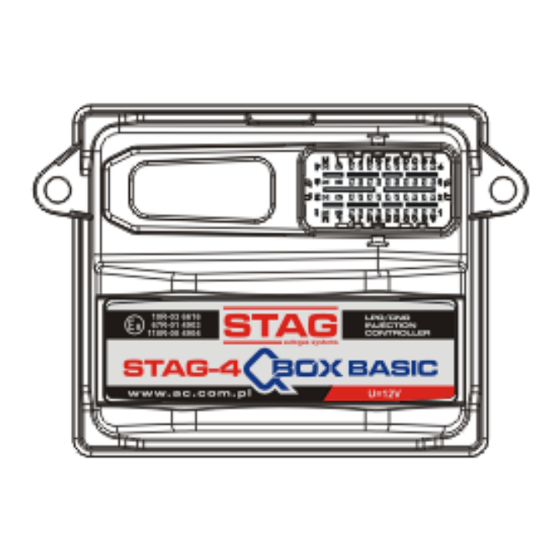
Controller User Manual
67R-01 4903
110R-00 4904
10R-03 6616
(information contained in this manual is also available
in the diagnostics software help system and at the
www.ac.com.pl
website)
ver. 1.7.9
2017-04-12
AC S.A. all rights reserved. Under penalty of law and/or liability claims it is forbidden to copy, publish, distribute, make available and/or use in any way all or any part of information contained
within this document, in particular photographs, drawings, illustrations, trademarks, etc.
Advertisement
Table of Contents

Summarization of Contents
Controller Installation and Diagrams
Layout Diagram STAG-4 QBOX BASIC
Diagram showing the wiring and component layout for the STAG-4 QBOX BASIC controller.
Layout Diagram STAG-4 QBOX PLUS
Wiring and component layout diagram for the STAG-4 QBOX PLUS controller.
Layout STAG-4 QNEXT PLUS
Diagram illustrating the wiring and component layout for the STAG-4 QNEXT PLUS controller.
Layout STAG-300 QMAX BASIC
Wiring and component layout diagram for the STAG-300 QMAX BASIC controller.
Layout STAG-300 QMAX PLUS
Diagram showing the wiring and component layout for the STAG-300 QMAX PLUS controller.
Wiring Diagram for Fuel Level Emulator FLE
Explains the wiring connections for the Fuel Level Emulator (FLE).
Wiring Diagram for Fuel Pressure Emulator FPE
Details the wiring connections for the Fuel Pressure Emulator (FPE).
Semi-sequential Control
Explains the semi-sequential injection control strategy for LPG systems.
Full-group Control
Describes the full-group injection control strategy for LPG systems.
Mounting Controller STAG-4 QBOX/QNEXT and STAG-300 QMAX
Guidelines on where to mount the STAG controllers to avoid damage.
Selection of Pressure Regulator
Advice on selecting the correct pressure regulator based on engine power.
Selection of Injector Nozzles
Guidance on selecting injector nozzles based on engine power and cylinder.
AC STAG Diagnostic Program
Controller-Computer Connection
Instructions on how to connect the controller to a PC via RS, USB, or Bluetooth.
AC STAG Version Information
Information on how to check the version of the AC STAG diagnostic application.
Main Menu Options
Overview of the options available in the main menu of the diagnostic program.
Controller Parameters Configuration
Details on essential parameters to configure for the vehicle's engine.
Signals, Injectors, and LED Switchboard
Explains the signals displayed in the monitor window and injector icons.
Auto-Calibration Procedure
Procedure for calibrating the engine at idle run using the auto-calibration function.
Oscilloscope Window
Describes the oscilloscope window for analyzing vehicle working conditions.
Error Handling and Reporting
Overview of how errors are displayed and categorized in the Errors tab.
Multiplier Map Usage
Explains the multiplier map for adjusting gas injection based on petrol injection time.
Multiplier Matching Function
Details how to match multipliers based on petrol and gas map deviations.
RPM Correction Map
Correction map to adjust multiplier based on engine revolutions and injection time.
Petrol Portion Map
Map for configuring petrol post-injection with simultaneous gas injector control.
Gas Temperature Correction Map
Map for automatic gas injection time correction based on gas temperature.
Reducer Temperature Correction Map
Map for adjusting multiplier based on reducer temperature.
Gas Pressure Correction Map
Map for manual percentage correction based on gas pressure.
Petrol Map 'B'
Preview of the petrol injection time map acquired while driving on petrol.
Petrol Map 'G'
Collection of petrol injection times for various engine speed and suction pressures on LPG.
Map Acquisition State
Preview of map data acquisition status, showing acquired sections.
Injection Time Deviation Map
View of differences between petrol and gas injection time maps.
MAP Correction Map (Autoadaptation)
Map for autoadaptation or manual correction of gas dosing based on RPM and load.
OBDII/EOBD Reader Functionality
Integrated reader for parameters and faults via OBDII/EOBD interface.
Digital Recorder
Records electrical pulse curves of injectors or RPM signals versus time.
Assignment of Gas Injectors to Banks
Procedure to assign gas injectors to specific banks for V and boxer engines.
Autoadaptation Mechanism
Mechanism for real-time gas dosing correction during driving.
ISA3 Autoadaptation Mode
Mode where controller adjusts gas dose based on a reference petrol map.
OBD Autoadaptation Mode
Mode where gas dosage correction is based on OBDII/EOBD interface parameters.
Controller Software Update
Steps to update the controller's firmware using the diagnostic software.
Diagnostics and Service Functions
Overview of diagnostic tests and service functions for controller components.
Diagnostics (Test Actuators)
How to perform basic tests on selected components like injectors and solenoid valves.
Service Function
Function to burn gas from the system before replacing filters.
Controller Programming Procedures
Auto-Calibration Process
Process for calibrating the engine at idle run for optimal LPG performance.
Petrol Map Collection (Petrol)
Procedure for collecting the petrol map by driving the vehicle.
Petrol Map Collection (LPG)
Procedure for collecting the LPG map under similar conditions as the petrol map.
Map Matching and Deviation Check
How to check and verify deviations between petrol and LPG maps.
Manual Controller Setting
Manual method for setting controller parameters, requiring sufficient experience.
LPG Temperature Correction
Correcting LPG temperature calibration when petrol injection time changes.
Intelligent Gas Level Indicator
Function for more precise gas level indication, independent of terrain slope.
LED Switchboard and Acoustic Signals
LED-300 Switchboard Operation
Explanation of the LED-300 switchboard's indicators and button functions.
LED-300/401B and LED-401 Switchboards
Details on LED-300/401B and LED-401 switchboards, including gas level and operating status indicators.
Automatic Calibration of LPG Level Indicator
Procedure for automatic calibration of the LPG level indicator.
Acoustic Signals
Description of various acoustic signals emitted by the controller.
Emergency Start on Gas
How to start the engine on gas in emergency mode.
Bluetooth Communication Interface
Information on setting up and securing the Bluetooth interface for controller configuration.


Need help?
Do you have a question about the STAG-300 QMAX BASIC and is the answer not in the manual?
Questions and answers