Table of Contents
Advertisement
Quick Links
Advertisement
Table of Contents

Related Manuals for Acowa ZOO

Summary of Contents for Acowa ZOO
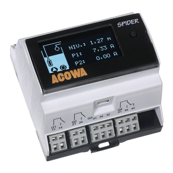
- Page 1 User manual ACOWA SPIDER / ACOWA ZOO August 2019...
-
Page 2: Table Of Contents
SPIDER diodes ............................8 Menu structure for the 2,4” OLED Display ....................9 HMI display ..............................9 I/O module ..............................10 ACOWA ZOO Configuration Tool ........................11 Connecting to a PC ............................11 USB connection ............................11 TCP Connection ............................11 ACOWA ZOO Installation .......................... - Page 3 Digital Inputs (I1–I6) ..........................17 Digital output ............................... 19 Device settings / advanced settings ......................22 Reports and alarms: ..........................22 Reverse Comm: ............................22 Show Status ..............................24 Online status ............................24 Applications ..............................25 Pump control: ............................25 Flow interface: ............................
-
Page 4: Spider
• Daily depth pumping to avoid top sediment layer. • Choice of various start levels to prevent sediment accumulation at liquid entrance point. • Configuration of SPIDER via ACOWA ZOO software, both locally (Micro USB cable) or via server setup. -
Page 5: Installation
IP20 Start-up time total 20-120 sec. (depending on the GSM network) Build-in power supply SPIDER has an internal power supply designed for supplying sensors and input and output signals. Power supply output + V: Output voltage 24 V DC Output current Max. -
Page 6: Analog Input
Analog input SPIDER is designed with one analog input 0 ... 20 mA / 4 … 20 mA. Numbers of analog mA inputs Electrically isolated Measuring range 0 / 4 – 20mA Input impedance Approx. 100 Ω Measuring accuracy +/- 1% af FS Signal area 0-24mA / 0 –... -
Page 7: Operation
Power supply The red button SPIDER has a red button on the print next to the SIM card where it is possible to restart / reset SPIDER. The red button on the top print has the following functions: The number of... -
Page 8: Spider Diodes
SPIDER comes with two different types of displays but can also work without a display. Display for direct mounting on SPIDER is a 2.4 "OLED display. The display has different screen settings and can be operated with the joystick on the right side. -
Page 9: Menu Structure For The 2,4" Oled Display
Menu structure for the 2,4” OLED Display HMI display SPIDER can also be delivered with a larger 7” HMI display where a larger graphic image can be designed. It is possible to design customized graphics. A serial overprint is required. This is easily clicked on the SPIDER as well as cable sets and HMI display. -
Page 10: I/O Module
I/O module For connections of further signals, it is possible to connect an I/O module with multiple digital and analog inputs. -
Page 11: Acowa Zoo Configuration Tool
To connect to ACOWA ZOO via TCP, it must first be set to the correct TCP settings (IP Address, Port, APN). This is done in the ACOWA ZOO via the USB port. Once the SPIDER is configured correctly, then it can be accessed from the ACOWA ZOO via TCP. - Page 12 Choose ”Install” Choose whether to start ACOWA ZOO-Tool after installation. Then choose ”Finish”...
-
Page 13: Acowa Zoo
SPIDER details (see page 15) Function buttons Functions associated with writing and reading from SPIDER and disk, as well as contact with SPIDER via TCP. Load Config from Device. Load settings from the connected SPIDER device. Write Config to Device. -
Page 14: Settings Selection
Select and load a typical SPIDER configuration (control of 1 or 2 pumps, groundwater lowering, etc.) Backup operations Mirrors the counters etc. in the SPIDER controller. (Is used for updating or replacement of the modem) Device settings Advanced settings. (Further description on page 22.) Show status. -
Page 15: Spider Details
Settings selection (see above) Analog Input (AI1) The analog input in the SPIDER is a standard 0-20 / 4-20 mA input to which a pressure transmitter or other measuring equipment can be connected. The input functions can be set in ACOWA ZOO when AI1 is selected in the Settings selection. AI 1 contains... - Page 16 AI 1 Settings Functions Description 0-20 mA or 4-20 mA Scaling input defined by measurement equipment Minimum scaling Minimum measurement reading value With 2 decimals (500 = 5,00) Maximum scaling Maximum measurement reading value With 2 decimals (500 = 5,00) High limit in use Activates high limet functions 0=disabled, 1=actiivated...
-
Page 17: Digital Inputs (I1-I6)
Digital Inputs (I1–I6) The I1-6 inputs on the SPIDER are standard 0-10 V inputs, or standard digital inputs where “0” is <5V and “1”> 12V. The input functions can be set in ACOWA ZOO when I1-6 is selected in the Settings selection. I1-... - Page 18 High-level switch: Used as a start signal for emergency control of the pumps in case of faulty level transmitter. The state of the high-level switch can be read on the Spider status word bit 26. Pump running P1/P2: used as feedback signal for the pump control. If the corresponding output on SPIDER is drawn, but the operating signal fails for more than 1 min.
-
Page 19: Digital Output
“dry running” of pumps, where a mechanical stop is activated and stops the pumps. Digital output DO 1-2 are relay outputs dedicated to pump control, where DO 3-4 is used for specialized functions. To configure DO 1-4 click on the button shown below the Spider image. DO 1 and 2 settings Functions Description... - Page 20 Aumagear: This function is yet to be implemented Bassin-PST: This feature requires that a VI6 level sensor is fitted to the SPIDER. The level sensor has its own start/stop levels set in addresses 2785 and 2786. If the level in the pump sump detects a high limit of the level, the basin pump will stop.
- Page 21 P1 and P2. Vacuum Pump: This special feature is limited and to DI3 on the SPIDER-I/O and DO4 on the SPIDER. If the instantaneous status of DI 3-SPIDER I/O goes high, DO4 is started and runs until the instantaneous status of DI3-SPIDER I/O goes low.
-
Page 22: Device Settings / Advanced Settings
This results in the following window. Reports and alarms: If the SPIDER is used as a stand-alone device that is not connected to a SCADA system, it is possible to receive a daily status SMS and alarm SMS in case of an alarms. - Page 23 1 decimal the flow values are multiplied by 10 in the table. NOTE: it is important to start with a data set in the table that is NOT (0,0) as the SPIDER perceives (0,0) as being the end of the table.
-
Page 24: Show Status
On the right side, the clock in the SPIDER can be read, as well as the IP address and signal strength. It is possible to set the clock in the SPIDER by clicking on the window over time. You can also reset the modem in the SPIDER by clicking on the "Reset Modem"... -
Page 25: Applications
SPIDER finds the longest pump cycle for a day, calculates pump capacity and inlet time, and stores this value as the current candidate. After 5 days. The candidates are evaluated, and the SPIDER finds the most... -
Page 26: Additional Options
Daily emptying: It is possible to have SPIDER run an emptying function at a fixed time of day. You put a check mark in "Daily emptying on/off" and enter the desired time of day. For example, the value 915 will be perceived as the time 9:15. -
Page 27: Monitoring
Geni ground water lowering: Used with Grundfos CUE converter. The SPIDER controls the CUE via GENIbus. Be aware that it is not possible to use this function together with a display of any kind. VLT ground water lowering: Used with Danfoss converter with a ModBus communication module. -
Page 28: Register List Quick-Guide
Register list quick-guide Analog Signal FP32S FP32S FP32S FP32S Pumping station Actual value Max. yesterday High limit Low limit AI 1 Level Phone: VI 1 VI 2 Port VI 3 VI 4 Funktion Pump control VI 5 Alarm number VI 6 Input Signal FP32U... - Page 29 Pump control FP32U FP32U FP32 FP32U FP32U FP32U FP32U FP32U FP32U Latest Latest Total Quantity Quantity Current Min. current operating Outlet flow Inlet flow capacity quantity today yesterday time Pump 1 Pump 2 Common Low current limit (Amps Current with 1 from energy Calculated Calculated...
- Page 30 Hour Month Year System information FP32U Id number GSM-signal Description 0-100% (0 decimals) SPIDER status: Register 92 Status Warning Alarm √ Bit 0: Emergency control active √ Bit 1: Emergence control actice 2 pumps √ Bit 2: Internal power supply failure √...
- Page 31 SPIDER status: Register 92 Status Warning Alarm √ Bit 20: Back-stop control P1 √ Bit 21: Back-stop control P2 √ Bit 22: Communication error CUE P1 √ Bit 23: Communication error CUE P2 √ Bit 24: Communication error HMI √...
Need help?
Do you have a question about the ZOO and is the answer not in the manual?
Questions and answers