Table of Contents
Advertisement
1.800.561.8187
TABLE OF CONTENTS
1.
Congratulations . . . . . . . . . . . . . . . . . . . . . . . . . . . . . . .3
2.
Product Description . . . . . . . . . . . . . . . . . . . . . . . . . . . .3
3.
Declaration of Conformity . . . . . . . . . . . . . . . . . . . . . . .4
SAFETY CONSIDERATIONS . . . . . . . . . . . . . . . .5
1.
Features and Benefits . . . . . . . . . . . . . . . . . . . . . . . . . .7
2.
Specifications . . . . . . . . . . . . . . . . . . . . . . . . . . . . . . . .8
D.
MEASUREMENT TECHNIQUES
1.
Controls and Functions . . . . . . . . . . . . . . . . . .13
2.
Step by Step Procedures:
Measuring DC Volts . . . . . . . . . . . . .15
b)
Measuring AC Volts . . . . . . . . . . . . .16
c)
Measuring DC Amps . . . . . . . . . . . .17
d)
Measuring AC Amps . . . . . . . . . . . .18
e)
Measuring Resistance . . . . . . . . . . .19
f)
Measuring Diodes . . . . . . . . . . . . . .20
g)
Continuity Buzzer . . . . . . . . . . . . . .21
h)
Measuring Capacitance . . . . . . . . . .22
i)
Measuring Frequency . . . . . . . . . . .23
j)
Component Test . . . . . . . . . . . . . . .24
k)
Logic Test . . . . . . . . . . . . . . . . . . . .26
SPECIAL DMM FEATURES & FUNCTIONS . . . .27
D MODE FEATURES & FUNCTIONS . . . . . . . . .29
NORMAL MODE 440 APPLICATIONS . . . . . . . .35
I.
TREND MODE 440 APPLICATIONS . . . . . . . . . .38
GLITCH CAPTURE 440 APPLICATIONS . . . . . .39
ACCESSORIES . . . . . . . . . . . . . . . . . . . . . . . .40
MAINTENANCE . . . . . . . . . . . . . . . . . . . . . . . .41
M. RS-232C INTERFACE . . . . . . . . . . . . . . . . . . . .42
TROUBLE SHOOTING GUIDE . . . . . . . . . . . . . .44
www.
.com
page
4 2
information@itm.com
Advertisement
Chapters
Table of Contents

Related Manuals for TPI 440


Summarization of Contents
Introduction to the TPI 440
Product Congratulations and Warranty
Expresses thanks for purchasing and outlines the limited warranty period for the TPI 440.
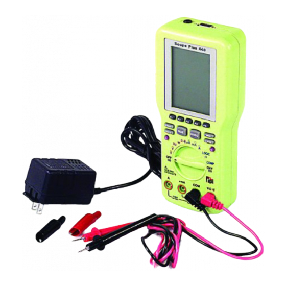
TPI 440 Product Overview
Describes the TPI 440 as a hand-held oscilloscope and autoranging DMM, highlighting key features and accessories.
EC Declaration of Conformity
Certifies the instrument's compliance with EMC and Low Voltage directives based on specified European standards.
Safety Considerations for Instrument Use
General Safety Precautions
Essential guidelines for safe operation, including pre-use checks and circuit understanding.
Critical Safety Warnings
List of actions to strictly avoid, such as measuring unknown voltages or improper current connections.
Technical Data and Specifications
Key Features and Benefits
Highlights major features like True RMS, Auto Set, Glitch Capture, Relative Mode, and Backlight.
Oscilloscope Function Specifications
Details specifications for oscilloscope functions including horizontal sweep rate, record length, and vertical resolution.
Oscilloscope Function Details
Further specifications on oscilloscope triggering, sensitivity, and glitch capture capabilities.
Digital Multimeter Function Specifications
Specifications for DC Voltage (DCV) and AC Voltage (ACV) measurements from 20Hz to 50Hz.
Digital Multimeter Measurements
Specifications for AC Voltage (ACV) across various frequencies, DC/AC Current (DCA/ACA), and Resistance (OHM).
Capacitance, Frequency, and General Specs
Specifications for Capacitance, Frequency measurements, and general instrument parameters like bandwidth and operating temperature.
Measurement Techniques and Instrument Operation
Instrument Controls and Functions
Explains the purpose and operation of the instrument's push buttons and rotary switch.
Rotary Switch Measurement Functions
Details the specific measurement functions (V, Ω, Diode, µA, mA, A, Hz, Logic) selected by the rotary switch.
Test Lead Input Jacks
Describes the function of each input jack (COM, A, µA/mA, VΩ) for connecting test leads.
DC Voltage Measurement Procedure
Step-by-step instructions for safely and accurately measuring DC voltage.
AC Voltage Measurement Procedure
Step-by-step instructions for safely and accurately measuring AC voltage.
DC Current Measurement Procedure
Step-by-step instructions for safely and accurately measuring DC current in series.
AC Current Measurement Procedure
Step-by-step instructions for safely and accurately measuring AC current in series.
Resistance Measurement Procedure
Procedure for measuring resistance, including notes on accuracy and safety.
Diode Test Procedure
Procedure for testing diode forward and reverse characteristics to determine functionality.
Continuity Buzzer Function
Procedure for using the continuity buzzer to check for electrical continuity in circuits.
Capacitance Measurement Procedure
Procedure for measuring capacitance, emphasizing safe discharge of capacitors before testing.
Frequency Measurement Procedure
Procedure for measuring signal frequency, including warnings about input voltage limits.
Component Characteristic Test
Utilizing the component test to analyze passive components by plotting voltage vs. current.
Logic State Test Procedure
Procedure for checking the high/low logic states of ICs for TTL and CMOS circuits.
Special Digital Multimeter Features
Relative Mode (REL) for Comparisons
Using the relative mode to establish a reference for subsequent measurements and component matching.
Peak Hold for Max/Min Readings
Capturing and displaying the maximum and minimum readings during a measurement session.
Continuity Buzzer Activation
Activating the continuity buzzer function for resistance checks below 100 Ohms.
Record (REC) for Min/Max Tracking
Utilizing the record function to track minimum and maximum values over a specified period.
Relative Percentage (REL%) for Tolerance
Displaying measured values as a percentage of a stored reference for component tolerance checks.
Compare Mode (COMP) for Value Matching
Comparing measured values against a set reference value to identify matching components.
D Mode Features and Functions
Trend Mode for Signal Monitoring
Measuring functions over a period to monitor trends and changes in circuit behavior.
Oscilloscope Mode Operation
Instructions for entering and utilizing the oscilloscope mode for waveform analysis.
Oscilloscope Time Base Control
Adjusting the time base settings for optimal waveform display and sweep speed control.
Oscilloscope Trigger Settings
Configuring trigger slope and level to accurately capture specific waveform events.
Single Sweep Waveform Capture
Performing a single sweep of the measured parameter based on current time and trigger settings.
Glitch Capture for Spike Detection
Using the glitch capture feature to detect and display short-duration spikes or anomalies in signals.
Waveform and Setup Memory Management
Waveform Memory Management
Procedures for saving, loading, and managing waveform data in the instrument's memory.
Setup Memory Management
Procedures for saving, loading, and managing instrument configuration settings in memory.
Editing Setup Configuration Parameters
Guide on how to edit various setup parameters such as range, contrast, and D Mode settings.
Setting REL% and COMP Reference Values
Instructions for setting reference values used in Relative Percentage and Compare modes.
Normal Mode Application Examples
Industrial Motor Control Applications
Utilizing the instrument for analysis in industrial motor control systems.
Power Quality Monitoring Applications
Applications for monitoring and analyzing power quality in electrical systems.
NC Machines Applications
Using the instrument to test and analyze functions within NC machines.
Uninterruptible Power Supply Applications
Applications related to testing and monitoring Uninterruptible Power Supplies (UPS).
Audio Equipment Applications
Using the instrument for testing and analyzing audio equipment signals.
Video Signal Analysis Applications
Applications for analyzing video signals, including scan rates and luminance.
Factory Automation Applications
Utilizing the instrument for testing and analysis in factory automation environments.
Line Conditioner Applications
Applications for testing and analyzing the quality of line conditioners.
Voltage Regulator Applications
Using the instrument to test and analyze voltage regulators for noise and stability.
Inverter Applications
Applications for testing the waveform quality of inverters.
Trend Mode Setup and Applications
Trend Mode Setup and Configuration
Step-by-step guide to configure the instrument for Trend Mode signal monitoring.
Trend Mode Application Examples
Specific applications where Trend Mode is beneficial for monitoring signal changes over time.
Glitch Capture Setup and Applications
Glitch Capture Setup and Configuration
Step-by-step guide to configure the instrument for Glitch Capture to detect signal spikes.
Glitch Capture Application Examples
Specific applications where Glitch Capture is used to identify and analyze signal anomalies.
Instrument Maintenance Procedures
Battery Replacement Procedure
Instructions for replacing the instrument's battery pack, including warnings and part number.
Fuse Replacement Procedure
Instructions for replacing internal fuses in the instrument's protected jacks.
Instrument Cleaning Instructions
Guidelines for cleaning the exterior surfaces of the instrument using mild detergent.
RS232 Communication and Software
RS232 Communication Hardware Requirements
Specifies the necessary hardware components for installing the software and establishing PC communication.
RS232 Software Installation Guide
Step-by-step instructions for installing the instrument's software on a PC.
Establishing PC Communication Link
How to connect the instrument to a PC via the RS232 cable and select the correct COM port.
RS232 Software Feature Descriptions
Explanation of software buttons and features for data management, printing, and screen capture.
Need help?
Do you have a question about the 440 and is the answer not in the manual?
Questions and answers