
Related Manuals for Biorock ECOROCK-2000


Summary of Contents for Biorock ECOROCK-2000
- Page 1 INSTALLATION & USER GUIDE FOR THE BIOROCK SYSTEMS: ECOROCK-1500 ECOROCK-2000 ECOROCK-3000 1 / 51 Installation and User guide – ECOROCK - Systems – 26-05-2016 PAGE...
- Page 2 TABLE OF CONTENTS INSTALLATION GUIDE ......5 USER GUIDE ........... 23 APPENDICES .......... 34 2 / 51 Installation and User guide – ECOROCK - Systems – 26-05-2016 PAGE...
- Page 3 The installation and commissioning of your BIOROCK® system should be carried out by a BIOROCK trained and approved installer. Your installer will be able to offer you a maintenance contract. The BIOROCK Warranty is only valid if the required maintenance is carried out by a BIOROCK trained and approved installer.
- Page 4 A. INSTALLATION GUIDE A. INSTALLATION GUIDE ECOROCK SYSTEMS 4 / 51 Installation and User guide – ECOROCK - Systems – 26-05-2016 PAGE...
-
Page 5: Table Of Contents
Installation layout n°1.: Gravity discharge (non-electric) ........... 10 Installation layout n°2.: Pumped discharge (pump after PT) ........10 Installation layout n°3.: Pumped discharge (pump after BIOROCK® unit) ....10 4. INSTALLATION OF THE TANKS ................11 Principles and constraints of installation works ............12 4.1.1... -
Page 6: The Biorock Sewage Treatment System
BIOROCK® biological purification process. The ECOROCK sewage treatment unit is exclusively designed for domestic waste water purification. The BIOROCK® plant consists of a Primary Tank and a ECOROCK Bioreactor. Both parts (Primary Tank and Bioreactor) must be ventilated. -
Page 7: Identification
Before installing please copy the serial number of each tank on to the documents to be kept by the customer (Appendix 5 of this Guide.) When looking at the tank facing the BIOROCK® logo, the serial number is: - On an identification tag inside the tank, and... -
Page 8: Operating Principles Of Your Biorock® System
Performance of the Primary Tanks (PT) If you don’t use a Primary Tank of BIOROCK, you have to make sure that the quality of the effluent of the PT meets the BIOROCK requirements. A proper ventilation of a PT is necessary, not only to avoid smell problems, but also to evacuate the produced gasses. -
Page 9: Biorock® Treatment Unit - Operating Principle
The pre- treated water is spread over the surface of the first layer of BIOROCK® media by a distribution system and penetrates into the media for purification. -
Page 10: Installation Layouts
A. INSTALLATION GUIDE > 3. INSTALLATION LAYOUTS 3. Installation layouts The installation of the BIOROCK® system depends on the available site, gradient, type of ground, the level of the water inlet and the discharge options. When the outlet for final effluent is not accessible, a sampling shaft should be installed. -
Page 11: Installation Of The Tanks
INSTALLATION OF THE TANKS 4. INSTALLATION OF THE TANKS This chapter provides a guide to the installation and commissioning of the BIOROCK® system. This manual cannot be a substitute for documentation and instructions from manufacturers of non- BIOROCK® products integrated into the system by the user. -
Page 12: Principles And Constraints Of Installation Works
The distance between the side of the excavation and the tanks must be minimum of 300 mm Connections for the BIOROCK® system are made with flexible seals with a diameter of 110 mm Local rules and legislation should be respected 4.1.2 Installation of the Primary Tank... -
Page 13: Installation In Dry Ground Conditions
The BIOROCK® unit must be installed downstream of the Primary Tank The effluent from the Primary Tank should flow by gravity to the BIOROCK® unit The gradient of the treated effluent pipe to the BIOROCK® unit should be a minimum of 1% 4.2 INSTALLATION IN DRY GROUND CONDITIONS See Appendix «Installation in dry ground conditions»... -
Page 14: Installation Of The Tanks In Dry Ground Conditions
Do not compact the backfill material mechanically: compact manually. Backfilling around and filling both the Primary Tank and BIOROCK® unit with water should take place at the same time. Once the backfilling is finished and compacted, check the levels of the tanks again ... - Page 15 A. INSTALLATION GUIDE 4. INSTALLATION OF THE TANKS Perform the same work as in dry ground conditions with the additional recommendations and modifications below: For installations in a high water table area, ensure the adequate drainage of the excavation during installation ...
-
Page 16: Installation In Specific Sites
The thickness and structure of any retaining wall should be specified by a qualified engineer along with the method of construction and backfilling procedure. At the same time as backfilling around the Primary Tank and BIOROCK® unit both tanks should be gradually filled with clear water (increments of 300 mm) ... -
Page 17: Installations Under Roads, Courtyards Or Storage Areas
A. INSTALLATION GUIDE 4. INSTALLATION OF THE TANKS 4.5 INSTALLATION UNDER ROADS, COURTYARDS OR STORAGE AREAS Installation conditions: Roads, courtyards or storage areas: The installation will be carried out in accordance with the preceding paragraphs, taking into account the nature of the soil. For an installation under roads, courtyards or storage areas, a distribution slab of reinforced concrete should be constructed and placed above the tanks ... -
Page 18: Ventilation And Water Distribution
A. INSTALLATION GUIDE 5. VENTILATION AND WATER DISTRIBUTION 5. VENTILATION & WATER DISTRIBUTION Never smoke in the vicinity of the installation or sewage works in general. Never enter the tanks without taking the necessary safety precautions such as ventilation, air monitoring, air supply and other procedures as required. Always have someone else on site if entering confined spaces. -
Page 19: Ventilation Of The Biorock® Treatment Unit
5.2 VENTILATION OF THE BIOROCK® TREATMENT UNIT The BIOROCK treatment unit has a separate ventilation system The vent pipe for the BIOROCK unit must be independent of the properties soil vent pipe and must not be combined with the Primary Tank vent pipe. -
Page 20: Biorock® Media
Don’t touch the BIOROCK® Media and don’t clean the BIOROCK® if it’s not necessary. The top layer of the BIOROCK® Media may be rinsed if blocked or contaminated with solids. In this case we recommend taking out the upper bags, rinsing them (if possible) and placing them back. -
Page 21: Stopping And Restarting The System
The BIOROCK® system remains efficient after a shutdown period. CONFORMITY AND WORK COMPLETION In all cases, the owner and the installer will jointly complete the installation checklist for BIOROCK® Sewage Treatment Plants (Appendix 5) and send it back to the manufacturer at the address listed. -
Page 22: Warranty
The ECOROCK-5000 units should never be laid on their side. In case of bad shipment or other damage, the BIOROCK® Media should be removed and replaced correctly as shown in the User Guide. - Page 23 B. USER GUIDE B. USER GUIDE FOR THE BIOROCK SYSTEMS: ECOROCK-1500 ECOROCK-2000 ECOROCK-3000 23 / 51 Installation and User guide – ECOROCK - Systems – 26-05-2016 PAGE...
- Page 24 2.2.1. Energy recovery .....................27 2.2.2. Material recycling ..................27 2.2.3. The BIOROCK® Media ..................27 3. OPERATING AND MAINTENANCE INSTRUCTIONS ..........28 Primary Tank and Effluent filter ...................28 ECOROCK® Treatment Unit...................31 24 / 51 Installation and User guide – ECOROCK - Systems – 26-05-2016...
-
Page 25: Safety Instructions
NOTE: Do not put your head directly into the septic tank or BIOROCK® through the manhole even to "have a look" or in an effort to find the cause of a malfunction. Noxious gases may accumulate in the system and may interfere with respiration and cause nausea, dizziness and in very extreme cases loss of consciousness. -
Page 26: Sustainable Development
All materials used in the manufacture and assembly of the BIOROCK® systems equipment are corrosion-resistant to ensure a long term installation. The main components are polyethylene (Tanks), PVC (piping) and the BIOROCK® media. Nearly 100% of the components can be recycled. 2.1 USEFUL INFORMATION 2.1.1 Sustainability... -
Page 27: Polyethylene And Pvc
2.2.3 The BIOROCK® media The BIOROCK® media is inert but if there is a need to replace some of the media the dirty bags (once removed) must be cleaned before recycling. The used BIOROCK® Media can be returned to the BIOROCK® Head Office for recycling. -
Page 28: Operating And Maintenance Instructions
Contact your dealer if necessary or contact us for more details about the closest dealer to you. The summary below indicates the commissioning of your sewage treatment plant. Your sewage treatment plant can be free from any failures as the BIOROCK® system does not require electricity. (In normal operation, and following the maintenance recommendations) - Page 29 Please check how often you need to empty your Primary Tank in line with local regulations. Please check if the Primary Tank has the required efficiency that is required by BIOROCK. See page 9, Chapter 2.1. MAINTENANCE GUIDE FOR THE PRIMARY TANK (PT) AND THE EFFLUENT FILTER (EF)
- Page 30 RECOMMENDATIONS FOR OPERATION AND MAINTENANCE Effluent Filter cleaning and replacement The BIOROCK® effluent filter does not need to be cleaned. We advise you to replace it when the Primary tank is emptied, or when the filter is clogged, or after two years.
-
Page 31: Ecorock® Treatment Unit
RECOMMENDATIONS FOR OPERATION AND MAINTENANCE 3.2 THE ECOROCK® TREATMENT UNIT The 10 years warranty shall only apply if the annual maintenance is carried out by a BIOROCK® approved installer or supervised by a trained BIOROCK® Certified professional MAINTENANCE PLANNING FOR THE ECOROCK-5000 SEWAGE TREATMENT PLANT Only take a sample from running water. - Page 32 While replacing the bags of BIOROCK® Media, make sure that each layer of bags completely covers the surface of the unit, ensure that there is no free space between the bags. The bags of BIOROCK® Media should always overlap each other. Ensure that the aeration rings are put back to the same position and height.
- Page 33 If an inspection shows an increasing amount of suspended solids in the outgoing water (final effluent), or an accumulation of suspended solids at the top layer of BIOROCK® media, then the BIOROCK® media may need to be cleaned more thoroughly.
- Page 34 1.1 Drawing of an ECOROCK-1500 treatment unit (6PE) ........... 35 1.2 Aeration & Water distribution schematic of an ECOROCK-1500 (6PE) ....... 36 1.3 Cross section of the layers of BIOROCK® Media in an ECOROCK-1500 unit ....37 1.4 Drawing of an ECOROCK-1500 treatment unit (8PE) ........... 38 1.5 Aeration &...
-
Page 35: Drawing Of An Ecorock-1500 Treatment Unit (6Pe)
APPENDICES APPENDIX 1 Drawing of an ECOROCK-1500 treatment unit 35 / 51 Installation and User guide – ECOROCK - Systems – 26-05-2016 PAGE... -
Page 36: Aeration & Water Distribution Schematic Of An Ecorock-1500 (6Pe)
APPENDICES APPENDIX 1 Aeration and water distribution scheme (without pumping well) 36 / 51 Installation and User guide – ECOROCK - Systems – 26-05-2016 PAGE... -
Page 37: Cross Section Of The Layers Of Biorock® Media In An Ecorock-1500 Unit
APPENDICES APPENDIX 1 Drawing (Cross section) showing the layers of BIOROCK® Media in a ECOROCK-1500 unit 37 / 51 Installation and User guide – ECOROCK - Systems – 26-05-2016 PAGE... -
Page 38: Drawing Of An Ecorock-1500 Treatment Unit (8Pe)
APPENDICES APPENDIX 1 Drawing of an ECOROCK-1500 treatment unit 38 / 51 Installation and User guide – ECOROCK - Systems – 26-05-2016 PAGE... - Page 39 APPENDICES APPENDIX 1 Aeration and water distribution scheme (without pumping well) 39 / 51 Installation and User guide – ECOROCK - Systems – 26-05-2016 PAGE...
-
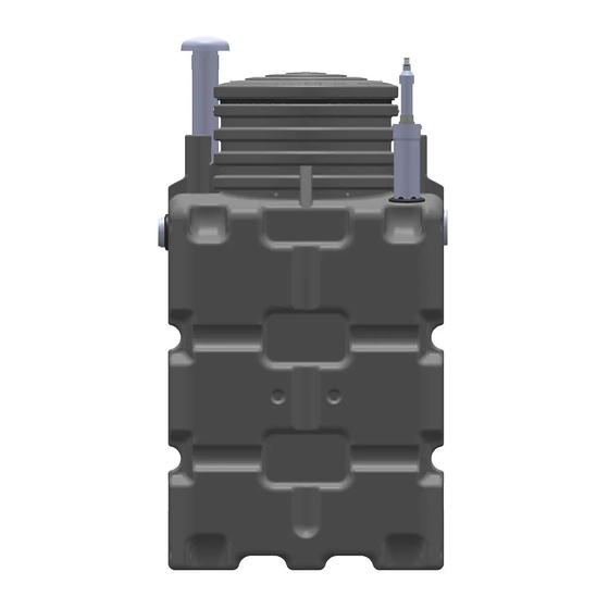
Page 40: Drawing Of An Ecorock-2000 Treatment Unit
APPENDICES APPENDIX 1 Drawing of an ECOROCK-2000 treatment unit 40 / 51 Installation and User guide – ECOROCK - Systems – 26-05-2016 PAGE... -
Page 41: Aeration & Water Distribution Schematic Of An Ecorock-2000
APPENDICES APPENDIX 1 Aeration and water distribution scheme (without pumping well) 41 / 51 Installation and User guide – ECOROCK - Systems – 26-05-2016 PAGE... -
Page 42: Cross Section Of The Layers Of Biorock® Media In An Ecorock-2000 Unit
APPENDICES APPENDIX 1 Drawing (Cross section) showing the layers of BIOROCK® Media in a ECOROCK-2000 unit 42 / 51 Installation and User guide – ECOROCK - Systems – 26-05-2016 PAGE... -
Page 43: Drawing Of An Ecorock-3000 Treatment Unit
APPENDICES APPENDIX 1 Drawing of an ECOROCK-3000 treatment unit 43 / 51 Installation and User guide – ECOROCK - Systems – 26-05-2016 PAGE... -
Page 44: Aeration & Water Distribution Schematic Of An Ecorock-3000
APPENDICES APPENDIX 1 1.10 Aeration and water distribution scheme (without pumping well) 44 / 51 Installation and User guide – ECOROCK - Systems – 26-05-2016 PAGE... -
Page 45: Cross Section Of The Layers Of Biorock® Media In An Ecorock-3000 Unit
APPENDICES APPENDIX 1 1.11 Drawing (Cross section) showing the layers of BIOROCK® Media in a ECOROCK-3000 unit 45 / 51 Installation and User guide – ECOROCK - Systems – 26-05-2016 PAGE... -
Page 46: Drawing (Cross Section) Of 1X Ecorock-1500 Plant In Dry Ground Conditions (6Pe)
APPENDICES APPENDIX 1 APPENDIX 2 46 / 51 Installation and User guide – ECOROCK - Systems – 26-05-2016 PAGE... -
Page 47: Drawing (Cross Section) Of 1X Ecorock-1500 Plant In Dry Ground Conditions (8Pe)
APPENDICES APPENDIX 2 APPENDIX 2 47 / 51 Installation and User guide – ECOROCK - Systems – 26-05-2016 PAGE... -
Page 48: Drawing (Cross Section) Of 1X Ecorock-2000 Plant In Dry Ground Conditions
APPENDICES APPENDIX 2 APPENDIX 2 48 / 51 Installation and User guide – ECOROCK - Systems – 26-05-2016 PAGE... -
Page 49: Drawing (Cross Section) Of 1X Ecorock-3000 Plant In Dry Ground Conditions
APPENDICES APPENDIX 2 APPENDIX 2 49 / 51 Installation and User guide – ECOROCK - Systems – 26-05-2016 PAGE... -
Page 50: Registration Form For Your Biorock® Plant
APPENDICES APPENDIX 4 MAINTENANCE AND ACTIONS FORM To be completed – TO BE KEPT BY THE USER DATE OF FIRST COMMISSIONING: ….…… / …….… / ………. Product N° of tank: (see page 9 in the user’s guide) Warning: Please keep sludge emptying documents and proofs validated by the contractor. DATE WHAT HAS BEEN DONE USER’S NAME... -
Page 51: Appendix
APPENDICES 51 / 51 Installation and User guide – ECOROCK - Systems – 26-05-2016 PAGE...
Need help?
Do you have a question about the ECOROCK-2000 and is the answer not in the manual?
Questions and answers