
Related Manuals for 4-acoustic SX-46000


Summary of Contents for 4-acoustic SX-46000
- Page 1 Pro Audio Germany acoustic Operation Manual SX-25000 SX-44000 SX-46000 4-acoustic .com SX-Series Operation Manual REV01 0820...
-
Page 2: Table Of Contents
7.2) SX-25000 Back Panel ......................... Page 9 7.3) SX-44000, SX-46000 Front Panel ....................Page 10 7.4) SX-44000, SX-46000 Back Panel ....................Page 10 7.5) SX-25000 DIP Switch Setting ....................Page 11 7.6) SX-44000, SX-46000 DIP Switch Setting................... Page 12 8.) Connecting 8.1) AC Mains Connection ........................ -
Page 3: Important Safety Instructions
1.) Important Safety Instruction 1.1) EXPLANATIONS OF GRAPHICAL SYMBOLS The triangle with the lightning bolt is used to When the unit is installed in a cabinet or a alert the user to the risk of electric shock. shelf, make sure that it has sufficient space on all sides to allow for proper ventilation. -
Page 4: Explanations Of Risk
22. The US National Differences clause 16.3 requires moving the cart/apparatus combination to avoid that network cables must be flame rated VW-1. injury from tip-over. 13. Unplug this apparatus during lightning storms or when unused for long periods of time. 4-acoustic Page 4 of 24 .com... -
Page 5: Declarations
(2) this where you can send your waste equipment for recycling, device must accept any interference received, including please contact 4-Acoustic or one of your local distribu- interference that may cause undesired operation. tors. -
Page 6: Welcome
3.) Welcome Welcome at 4-Acoustic Thank you for selecting our SX-Series amplifier for your sound system demand. We are confident that you will be satisfied with the professional features, excellent perfor- mance and reliable durability offered by this series. 4-Acoustic SX-Series amplifiers can be used in an unlimited range of PA applications such as touring, clubs, opera houses, theaters, churches, cinema, and theme parks. For safe installation and use of this amplifier please study this operation manual thoroughly to become acquainted with the basic configuration and control options available. It provides a brief introduction to the features and functionality of the SX-Series amplifier, and it also contains the information required to safely install the product and place it in ser- vice. -
Page 7: Unpacking
(See Figure 5.1) diately inspect your new amplifier. Note: Instead of connecting the amplifier to the power grid Your 4-Acoustic amplifier has been completely tested directly, plug the amplifier’s mains connections to a power and inspected before leaving the factory. -
Page 8: Dimensions
6.) Dimensions 6.1) SX-25000 Dimensions CH A CH B BRIDGE PARALLEL PROTECT MODE OUT B OUT A+B MAINS IN SENSITIVITY STEREO OUT B OUT A ON ON ON ON ON ON ON ON ON ON 2,0V 1,4V 1,0V 0,775V PARALLEL... -
Page 9: Controls And Indicators
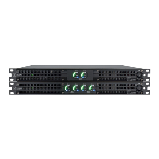
7.) CONTROLS AND INDICATORS 7.1) SX-25000 Front Panel CH A CH B POWER PROTECT A - Level and Signal Indicators C - Power CH 1/2 Indicator Illuminates when power supply is activated for LEDs indicate signal presence and level as follows: channel 1/2. -
Page 10: Sx-44000, Sx-46000 Front Panel
I - Cooling Fan Outlet per channel). The signal at these connectors is paralleled Outlet for cooling air flow. Do not block or cover this outlet with the input signal for feeding the input signal to other amplifiers. 4-acoustic Page 10 of 24 .com... -
Page 11: Sx-25000 Dip Switch Setting
7.) CONTROLS AND INDICATORS 7.5) SX-25000 DIP Switch Settings The two-channel model SX-25000 has control options for the Input sensitivity and the signal input mode of the XLR input sockets CHA and CHB. Sensitivity Switches: Select between four different input sensitivity level with the two dip switches 1 and 2. (0,775V/1,0V/1,5V/2V) Figure 7.1 shows how to select the right setting. -
Page 12: Sx-44000, Sx-46000 Dip Switch Setting
Input Socket CHD connected CHD Input Socket CHA connected CHA Bridge CHA / CHB Input Socket CHA connected CHB 2,0V Input Socket CHB connected CHC Bridge CHC / CHD 7 8 9 10 Input Socket CHC connected CHD 4-acoustic Page 12 of 24 .com... -
Page 13: Connecting
8.) CONNECTING 8.1) AC Mains Connection This amplifier comes with a power cord using a Neutrik Powercon® plug to connect to the amplifier and a power plug used in your country to connect to the mains. The AC mains voltage and current must be sufficient to deliver the power you need to drive this amplifier. -
Page 14: Audio Input Connection
Figure 8.4 shows male and female XLR connector pin assignment. Pre-build or professionally wired balanced cable (two-conductor plus shield) and connectors are recommended. (Figure 8.2) Unbalanced line (Figure 8.3) may also be used but may result in noise over long cable runs. 4-acoustic Page 14 of 24 .com... -
Page 15: Speaker Connection
Recommended are professionally wired, high quality, heavy gauge speaker wire and connectors with two or four conductors. Figure 8.5 shows the wiring with a 4-pole Speakon® connector. Figure 8.6 shows the connecting with banana plugs, spade lugs, or bare wire. (SX-25000 only) SHOCK HAZARD: When the amplifier is turned on and passing a signal potentially lethal voltages exist at the speaker output connectors. -
Page 16: System Setup
Turn off the amplifier and unplug its power cord. INPUTS: Connect analog input wiring for both channels. OUTPUTS: Binding posts outputs figure 9.1 (Only SX-25000) Connect Channel 1 loudspeaker’s positive (+) lead to Channel 1 positive (red) terminal of amp; repeat for negative (–). Repeat Channel 2 wiring as for Channel 1. Speakon® outputs figure 9.2 To wire stereo speakers to the Speakon®... -
Page 17: System Setup With 4-Wire Cable
9.) SYSTEM SETUP 9.2) System Setup with 4 Wire Cable Four wire system setups with subwoofer and Mid/High cabinet. Maintain proper polarity (+/–) on output and input connectors. Use Class 2 output wiring. IMPORTANT: Turn off the amplifier and unplug its power cord. INPUTS: Connect analog input wiring for both channels. -
Page 18: Subwoofer Setup In Bridge Mode
ON ON ON ON ON ON ON ON ON ON ON ON ON ON ON ON 2,0V 1,4V 1,0V 0,775V BRIDGE PARALLEL 1 2 3 4 5 6 7 8 9 10 Bridge Mode 4-acoustic Page 18 of 24 .com... -
Page 19: Four Channel Sound System
9.) SYSTEM SETUP 9.4) Four Channel Sound System (SX-44000 and SX-46000 only) Typically, four channel sound setups for monitoring, multi room usage, or line array cluster. Maintain proper polarity (+/–) on output and input connectors. Use Class 2 output wiring. IMPORTANT: Turn off the amplifier and unplug its power cord. -
Page 20: Two Channel Parallel Mode
CHC is internal connected with CHD (5/6) CH D CH A 2 Wire Cable 2 Wire Cable (1+/1-) (1+/1-) Channel D Channel A CH C CH B 2 Wire Cable 2 Wire Cable (1+/1-) (1+/1-) Channel C Channel B 4-acoustic Page 20 of 24 .com... -
Page 21: Stereo System Setup With Subwoofer And Mid/High Cabinets
9.) SYSTEM SETUP 9.6) Stereo System Setup 2 subwoofer and 2 Mid/High cabinets (SX-44000 and SX-46000) Stereo system setup with four channel amplifier and four wire cable. Two subwoofer and two Mid/High cabinets. Maintain proper polarity (+/–) on output and input connectors. Use Class 2 output wiring. IMPORTANT: Turn off the amplifier and unplug its power cord. -
Page 22: Setting System Gain Structure
To High Clip the DSP will clip Headroom 6dBu=1,54V Desired Output Level nominal operation 6dBu 6dBu Amplifier To low Noise Floor Noise level to high Audio Source Amplifier (Mixer) (DSM-428) Increase the sensitivy Amplifier 4-acoustic Page 22 of 24 .com... -
Page 23: Bridge Mode Function
9.) SYSTEM SETUP 9.8) Bridge Mode Function The SX-44000 and SX-46000 allows to set CHA/CHB and/or CHC/CHD into bridge mode. In this mode the input signal CHA and/or CHC will be internal inverted and used for the cooperating amplifier channel. The result at the output is a signal with twice the voltage of a single output in stereo or parallel mode. -
Page 24: Technical Specification
11.) Technical Specification Model Name SX-25000 SX-44000 SX-46000 GS1 (EAN) CODE 4260318511858 4260318512022 4260318511865 System Type 2-Channel Class D Amplifier 4-Channel Class D Amplifier 4-Channel Class D Amplifier Output Power all 2 x 6000W @ 2Ohm 4 x 2700W @ 2Ohm...
Need help?
Do you have a question about the SX-46000 and is the answer not in the manual?
Questions and answers