
Related Manuals for Mueller Fre-Heater D2-120


Summarization of Contents
Section 1.0 – Introduction
1.1 Description of the System
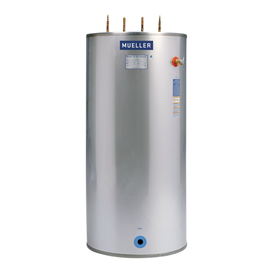
Provides a general overview of the Mueller Model "D" Fre-Heater's function and design.
1.2 Technical Support
Offers contact information for obtaining additional technical assistance from the manufacturer.
1.3 Capacity
Discusses unit sizing and how hot water generation varies with system parameters.
Section 2.0 – Installation
2.1 Inspection
Details the process of checking shipments for damage or shortages upon delivery.
2.2 Fre-Heater Location
Provides guidance on selecting an appropriate indoor location, considering weight and protection.
2.3 Leveling
Explains how to use provided cap screws and optional kits to level the Fre-Heater unit.
2.4 Installing Water Piping
Covers the connection of water inlet and outlet, including bypass lines and specific fitting advice.
2.5 Refrigeration Connections
Outlines the procedures and precautions for connecting refrigerant lines, emphasizing qualified technicians.
2.6 Heat Pumps
Discusses the use of Fre-Heaters with commercial heat pump systems and necessary precautions.
2.7 Ice Machines
Advises on installing Fre-Heaters with water-cooled and air-cooled ice machines.
2.8 Refrigerant Charge
Explains the process of checking and adding refrigerant charge to the system.
2.9 Test Run
Describes the final steps of checking leaks, charge, and controls after installation.
2.10 Electrical Connections for Model "DE" Fre-Heater
Details electrical hookups for the heating element and control circuits, emphasizing safety.
2.11 Special Model "DE" Fre-Heater Operating Instructions
Provides specific operating guidance for the electric heating element and safety warnings.
2.12 Maintenance
Lists annual maintenance tasks to ensure the longevity and proper function of the Fre-Heater.
Section 3.0 – Water Temperature Limit and Three-Way Heat Reclaim Valve
3.1 Solenoid Valve Installation
Covers the installation of the three-way heat reclaim valve, including refrigerant handling and location.
3.2 Aquastat Installation
Details the correct placement and installation of the Aquastat bulb and well.
3.3 Electrical Installation
Explains the electrical requirements for the three-way heat reclaim valves and Aquastat.
3.4 Checkout and Test Run
Describes the final checks and operational verification of the installed system.
Section 4.0 – Btuh Estimated Capacity
4.1 Btuh Estimated Capacity Information
Provides guidance on estimating heat recovery capacity based on various factors.
Section 5.0 – Fre-Heater Equipment Markings
5.1 Label No. 8801149, Warning: Disconnect Power Before Servicing
Safety warning about disconnecting power before performing any service on the unit.
5.2 Label No. 8802732, Warning: Pressure Relief Valve Must Be Installed
Warning emphasizing the mandatory installation of the pressure relief valve.
5.3 Label No. 8801888, Warning: Hot Water
Warns about the risk of severe burns from hot water produced by the unit.
5.4 Label No. 8800996, Copper Conductor
Instruction to use only copper conductors for electrical connections.
5.5-5.8 Connection Labels (Hot, Cold, In, Out)
Identifies basic connection labels such as Hot, Cold, In, and Out.
5.9 Label No. 8800215, Pressure Relief
Label for the pressure relief component.
5.10 Label No. 8822705, CSA LR 67608 and USK
Indicates CSA certification and listing information.
5.11 Label No. 8820623, Electrical Warning
General warning symbol for electrical hazards.
5.12 Label No. 8801408, Attention: Water Connections and Relief Valve
Important notes on water connections and relief valve installation and warranty.
5.13 Label No. 31246, Mueller Name Plate
Identifies the unit's manufacturer name plate.
5.14 Label No. 8823999, Attention: Control Circuit Wiring Specifications
Directs users to wiring diagrams for control circuit specifications.
5.15 Label No. 8824716, HFC Refrigerant
Identifies the type of refrigerant used (HFC) and oil type (POE).
5.16 Label No. 8820454, Important! Dry Nitrogen Gas
Important instructions regarding the dry nitrogen holding charge and system evacuation.
5.17 Label No. 8803611, Fre-Heater Model "DE" Data Plate
Details for the Model "DE" Fre-Heater data plate, including specifications.
5.18 Label No. 31433, Fre-Heater Model "D" Data Plate
Details for the Model "D" Fre-Heater data plate, including specifications.
5.19 Label No. 8824816, CRN
Provides CRN numbers for British Columbia and other provinces.
Section 6.0 – Appendix A
6.1 Thermal Expansion Tank Installation for Dairy Farm Applications
Details the requirement and installation of thermal expansion tanks for dairy farm applications.
Need help?
Do you have a question about the Fre-Heater D2-120 and is the answer not in the manual?
Questions and answers