Table of Contents
Advertisement
Advertisement
Chapters
Table of Contents

Related Manuals for Mirae Mx200


Summarization of Contents
Safety Instructions
Guidelines to Using this Manual
Explains the use of symbols, page numbering, figure numbering, acronyms, and bold text.
Chapter 1 Introduction
Overview of Operation Manual
Provides a general overview of the Operation Manual's content and structure.
Chapter 2 Specifications and Features
Introduction
Overview of the chapter's content covering features and specifications.
Features
General advantages and capabilities of the Mx-Series system, highlighting key benefits.
High Performance and High Efficiency
Details on gantry speed, precision, and placement capabilities.
High Productivity
Explains optimization, line balance, and off-line programming benefits.
User-friendly interface
Covers GUI, wizards, and help windows for ease of operation.
High Reliability
Focuses on precision linear motors and intelligent feeders.
Technical Specifications
Detailed technical data including tact time, accuracy, and dimensions.
Chapter 3 Installation
Packing List
Lists all spare parts included with the system.
Packing Procedure
Step-by-step guide on how the system is packed.
Equipment Shipping (Transportation)
Procedures for lifting and moving the packed system.
Equipment Unpacking
Steps for safely removing the system from its packaging.
Setup Environment
Specifies environmental conditions for installation (floor, temp, humidity, vibration).
Conveyance and Setup
Details on moving the machine and initial setup steps.
Compressed Air Specification and Connection
Requirements for compressed air supply.
SMEMA Connection
Information on connecting to post-process equipment.
Power Specification and Connection
Electrical power requirements and connection procedures.
Grounding
Guidelines for proper grounding of the system.
CIS-1: SETUP FLOW CHART (Utility)
A visual guide for the utility setup process.
CIS-2: SETUP FLOW CHART (Precision)
A visual guide for the precision setup process.
CIS-3: UTILITY & LINE LAYOUT
Checks for utility connections and line layout.
CIS-4: Assembly Check
Verifies correct assembly of components and the machine.
CIS-5: Operation & Parameters Check
Confirms system operation and parameter settings.
CIS-6: W/U, Dry run & Placement
Procedures for warming up, dry runs, and initial placement tests.
CIS-7: Problems & Requests
A form for documenting issues and requests during setup.
Chapter 4 Unit Description
Introduction
Overview of the chapter's content covering unit descriptions.
Structure and Configuration
Details on the overall structure and how units are configured.
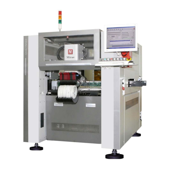
Appearance
Visual presentation of the machine's external components.
Structure
Describes the system's assemblies and their optimization.
Operation Flow
Step-by-step description of the machine's operation process.
PWB Transfer System
Explains the structure and function of the PCB conveyor system.
Component Feeding System
Details the feeder base, feeder, and intelligent feeder configurations.
Positioning System
Covers XY gantry, vision system, and nozzle units.
XY Gantry
Describes the structure, function, and specifications of the XY gantry.
Positioning Head
Details the types, functions, and placement system of the positioning head.
Vision System (Component Recognition)
Explains component recognition cameras and their functions.
Automatic Nozzle Changer (ANC)
Describes the function of the ANC for automatic nozzle changes.
Nozzle Unit
Details the standard nozzle units available for component placement.
Chapter 5 Preparation for Programming
Introduction
Overview of the chapter's content on programming setup.
Preparation for Operation
Checks to perform before switching on the machine.
Safety Instructions
Guidelines to ensure safety during operation.
Safety Cover
Describes the function and operation of the safety covers.
Emergency Push Button Switch
Details the function and usage of the emergency stop button.
Operation Procedure
Step-by-step guide for operating the machine.
System Connection Check
Verifies all system connections before operation.
Main Power On (PC Power)
Procedure for powering on the PC and logging into Windows.
System (Main Frame) Power On (Mx100/200)
Steps for powering on the main frame of the Mx100/200.
Test Run
Procedure for performing a test run of the system.
Chapter 6 Programming
Introduction
Overview of the chapter's content on programming.
Work Flow Chart
Visual representation of the programming workflow.
CAD Conversion
Procedure for converting CAD data into a Mirae system compatible format.
PWB Information
Entering and setting PWB configuration details for production.
Opening a Program
Steps to open an existing program or create a new one.
Related Position Setting
Setting PWB origin and fiducial mark information.
Fiducial Mark DB
Managing the database for fiducial marks used in placement.
Pick Data
Entering and verifying pick data for components.
Entering a New Part
Procedure for adding new part information to the database.
Using Comp DB Editor
Editing and managing component database entries.
Setting Other Part Information
Configuring feeder and reel information for parts.
Optimize
Performing line optimization and mounter optimization.
Mirae Optimizer Phoenix 1.0.0.8
Details on using the Mirae Optimizer software.
Part Inspection
Procedures for inspecting parts using the camera.
PIC Function
Using vision monitor for placement position check and compensation.
Chapter 7 Set Up
Machine Type Setting
Procedure to define the machine type via Mr.Terminal.
Check Options and Parameters
Verifying parameters and options using MSetup.
DMC Parameter Setting (Applicable model)
Defining DMC configurations using MonitorQ software.
Check Gain and Parameter Settings for XYRZ and Other Axes
Verifying parameters for XYRZ and other axes using MonitorQ.
Save DMC Parameters (Applicable model)
Saving DMC parameters for axis or DMC replacement.
Offset Camera Calibration
Calibrating the offset camera for accurate positioning.
Setting SW Limit and Z-Origin Offset
Setting origin offset and SW limits for gantry axes.
Machine Perpendicularity Calibration
Compensating gantry distortion using a calibration glass.
Camera Calibration
Performing calibration for various cameras.
Align Position Setting
Tuning to align coordinate systems recognized by different cameras.
Head Offset and Recognition Offset
Defining distances between cameras and Z-axis.
Appendix A: Mx-Series Specification Sheet
Mx-Series Specification Sheet-Mx100/P
Detailed specifications for Mx100/P models.
Mx-Series Specification Sheet-Mx200/P/TP
Detailed specifications for Mx200/P/TP models.
Mx-Series Specification Sheet-Mx400(S)/P(S)
Detailed specifications for Mx400(S)/P(S) models.
Glossary Abbreviation
List of acronyms and their meanings used in the manual.
Expandable Item List & Life Cycle
Information on expandable parts and their expected lifespan.
JIG List
List of specialized tools (JIGs) used for maintenance and setup.
I/O Map
Diagram illustrating the input/output connections and pin configurations.
BOM Tree
Bill of Materials showing the hierarchical structure of assemblies.
Block Diagram
Visual representation of system block diagrams and electrical circuits.
Need help?
Do you have a question about the Mx200 and is the answer not in the manual?
Questions and answers