Advertisement
Quick Links
M i c r o Ra g e A m p l i f i e r s
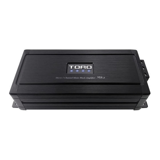
MR2
MRX2
MRX4
S
COMPACT FULL RANGE & CLASS D AMPLIFIERS
UPER MINI
Owners Manual
Please read through this manual to familiarize yourself with your new amplifier. Should your TORO
AUDIO mobile amplifier ever require service, you will need to have the original dated receipt.
Advertisement

Summarization of Contents
Technical Features
Installation Experience Required
Requires knowledge of electronic wiring and speaker impedance. Professional installation is recommended.
Preparing for Installation
Lists necessary tools for basic installation, including drills, screwdrivers, wire strippers, and soldering equipment.
Installation Precautions
General Precautions
Turn off devices, disconnect battery, locate hazards, ensure ventilation, use grommets, and wear protective eyewear.
Mounting the Amplifier
Guidance on physically securing the amplifier, including placement and avoiding damage during drilling.
Mounting Location
Mounting Location Details
Find a clear, ventilated area, protected from moisture and sun. Avoid carpets or stagnant air.
Mounting Warnings
Key warnings against upside-down mounting, subwoofer enclosures, unprotected connections, and improper terminal tightening.
Amplifier Functions
Speakers
Connect speakers/subwoofers using the Molex connector, ensuring proper polarity and no chassis ground connection.
+12 Volt Power
Connect to the positive terminal of the vehicle battery or isolated audio system battery via a fuse circuit breaker.
Auto Sensing Turn-On / REM Out
Detects DC offset for auto turn-on/off or uses REM IN for low-level input control.
GND (Ground)
Connect directly to stripped bare metal frame of the vehicle for a good ground connection.
RCA Input / Line Convertor
Connects to source unit RCA low-level outputs or high-level outputs via adapter for signal input.
Remote (MR2)
Connects the remote controller for adjusting amplifier volume from the driver's seat.
Gain Controller
Matches amplifier sensitivity to source unit signal voltage, not a volume control.
Low Pass Filter Control (MR2)
Selects desired low pass crossover frequency, adjustable from 60Hz to 220Hz for mono models.
Bass Boost Level Knob (MR2)
Adjusts bass boost level from 0 to 12dB for matching amplifier performance to subwoofer response.
X-Over Mode (MRX2)
Adjusts operating frequency range (LPF, HPF, FULL) for different speaker types and frequency response.
Frequency Control (MRX2)
Works with crossover switches for HPF/LPF frequency adjustments, with X1/X10 multipliers.
Power Protection Indicator
LED indicates proper operation (ON) or fault condition (flashing RED).
Clip Indicator
LED indicates signal clipping; lowering gain reduces clipping.
Crossover (MRX4)
Selects Low Pass Frequencies (LPF) for full range or specific crossover points.
High Pass Filter (MRX4)
Sets High Pass Frequency (HPF) from 20Hz-300Hz or bandpass from 20Hz-3kHz.
Power Wiring and Signal Connections
12V (Power) Connection
Connect directly to the vehicle battery via an in-line fuse or circuit breaker.
GND (Ground) Connection
Connect to a bare metal area on the vehicle chassis, preferably the floor pan.
REM (Remote Trigger) Connection
Connect to a switched +12V source for amplifier turn-on/off synchronization.
Fuse Requirements
Main power lead must be fused within 18 inches of the battery positive terminal.
Wiring Diagrams
Mono Amplifier Wiring (Single Woofer Load)
Diagram showing connections for a mono amplifier with a single woofer load.
Mono Amplifier Wiring (Multi-Woofer Load)
Diagram illustrating connections for a mono amplifier with multiple woofer loads.
MRX2 Amplifier Wiring (1-Channel Mode)
Wiring diagram for the MRX2 amplifier in 1-channel bridged mode.
MRX2 Amplifier Wiring (2-Channel Mode)
Wiring diagram for the MRX2 amplifier in 2-channel stereo mode.
MRX4 Amplifier Wiring (3-Channel Mode)
Wiring diagram for the MRX4 amplifier in 3-channel mode.
MRX4 Amplifier Wiring (4-Channel Mode)
Wiring diagram for the MRX4 amplifier in 4-channel mode.


Need help?
Do you have a question about the MRX4 and is the answer not in the manual?
Questions and answers