Table of Contents
Advertisement
Advertisement
Table of Contents

Related Manuals for ABB Symphony IMDSI22


Summarization of Contents
Preface
Introduction to Digital Input Modules
Introduces IMDSI13, IMDSI14, IMDSI22 modules and their role.
Safety Summary and Warnings
Electrostatic Sensitive Device (ESD) Precautions
Guidelines for handling static-sensitive devices to prevent damage.
Electrical Shock Hazard Warnings
Specific warnings and precautions regarding electrical shock hazards.
Section 1: Introduction
Overview of Digital Input Modules
Describes the IMDSI modules and their function in the Harmony system.
How to Use This Instruction Manual
Guidance on reading and following the manual's sections.
Glossary of Terms and Abbreviations
Defines terms and abbreviations used in the document.
Section 2: Description and Operation
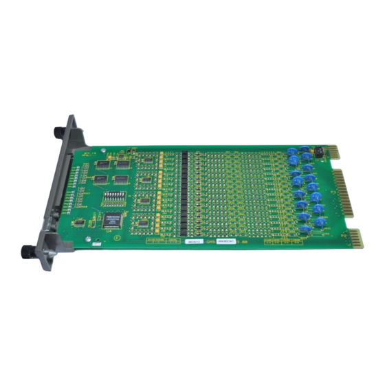
Module Description and Key Features
Details the physical characteristics and internal layout of the module.
Input Circuits and Signal Flow
Explains the input signal path, isolation, and detection circuitry.
Logic Power and I/O Expander Bus Interface
Describes logic power supply and I/O expander bus interface.
Section 3: Installation Procedures
Special Handling for Static-Sensitive Devices
Precautions for handling static-sensitive devices during installation.
Address Selection and Jumper Settings
Configuration of module address and input jumpers for voltage/mode.
Physical Installation and Wiring
Steps for mounting the module and making cable connections.
Section 4: Operating Procedures
Front Panel Indicators
Explanation of status LEDs on the module's front panel.
Startup Procedures
Details the automatic startup sequence managed by the controller.
Section 5: Troubleshooting
Error Indications and Controller Errors
Identifying errors and addressing controller-related issues.
Module Pin Connections Reference
Reference for pin assignments of module connectors.
Section 6: Maintenance
Preventive Maintenance Schedule
Recommended maintenance tasks and their frequency.
Cleaning Procedures for Boards and Connectors
Detailed steps for cleaning circuit boards and connectors.
Section 7: Repair and Replacement
Module Replacement Procedure
Step-by-step guide for replacing a faulty digital input module.
Appendix A: NTDI01 Termination Unit Configuration
Dipshunt Configuration for NTDI01
Details dipshunt settings for configuring digital input applications.
Need help?
Do you have a question about the Symphony IMDSI22 and is the answer not in the manual?
Questions and answers