Advertisement
Quick Links
Advertisement

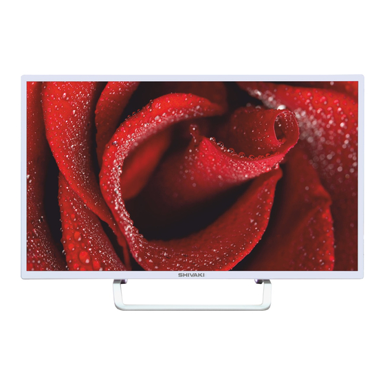
Summary of Contents for Shivaki STV-40LED13W
- Page 1 STV-32LED13/STV-32LED13W) STV-40LED13/ STV-40LED13W) Service Manual...
- Page 2 Contents 1. Safety precautions 2. Technical specifications, characteristics and functions 3. LCD structural diagram 4. Description of major components of LCD 5. Failure analysis 6. Simple adjustment 7. List of assemblies 1...
- Page 3 Note: This service manual should be read and used by the professional staff only. Prior to any repair work, the inspectors must read the safety precautions in this manual. Safety precautions ▲ It is strictly prohibited to place this unit in open air or damp places in order not to cause internal short-circuit firing or electroshock risk.
- Page 4 General rules: 1. Before the rear cover is opened for repair, the unit must be placed horizontally on a soft surface with no static charges. 2. Before the chassis are repaired (with power on), a 1:1 isolation transformer should be connected between the AC power supply and this unit. 3.
- Page 5 II. Technical performance STV-32LED13/STV-40LED13 is a high-definition color TV receiver that integrates modern electronic technology, communication technology, information processing technology and high-speed numeric picture processing technology. (I) technical specifications: Type STV-32LED13/STV-40LED13 Broadcasting signal PAL /SECAM DVB-T/T2 DVB-S/S2 system Video signal system...
- Page 6 (III) Major functions of this unit 1. This unit can control the application functions through the various infrared transmitting commands of the remote control. Name Function POWER Standby on/off SOURCE TV / VIDEO input status selection button MUTE Mute on/off DISPLAY The signal information SLEEP...
- Page 7 III. LCD structural diagram tructural diagram (see Attached sheet I) IV.Description of the major components (I) Printed circuit board: Name Printed circuit board No. Main Functions Mainboard A920326@ Is a board which is integrated with power (Printed Board No. supply,LED driver and TV board. TP.S512.PB83(80V/320mA)) Is an analog and digital TV control board, which is suitable for Pan-European...
- Page 8 (II) LCD display screen: Refer to the LCD specification (see the annex) (III) Instructions of main components: I. High-frequency tuner: 1) Radio frequency receiving and demodulation; 2) PAL/SECAM analog television and DVB-T , DVB-S2digital television 3) FS (Frequency Synthesize); 4) IIC control; 5) Integrated image middle-frequency demodulation, outputting full TV signal video and audio.
- Page 9 V. Failure analysis: Main failure analysis diagram (see Attached sheet IV) Common failures: Other failures Analysis procedure Image and Inspect if the direction, position and connection of the antenna is accompanying sound proper. are interfered. Inspect if the signal sources are inputted stably under the current playing status with no interference.
- Page 10 Perform failure analysis with the “Operation Instruction” used correctly: No raster If the power Power supply supply cable is cable plug and connected receptacle properly If the input voltage and Ensure the correct frequency is consistent input of power with those of the unit supply If the unit is in standby status (remote control...
- Page 11 Poor power supply Open the cover; switch . Need enter the start-up replacement. status; check the 100-220V~ voltage of power heck the Check the Replace the mainboard mainboard CN14 CNB806 input input mainboard voltage/current: voltage:1/2/3#- 80V/360mA Check if the Check the Replace the LT3247E/LT3947E mainboard CNK2:-...
- Page 12 Image available but accompanying sound not. Check if Start up and Check if the theCN16 sound volume check for connection wire can be set. of mainboard is no noise. well connected? Replace the mainboard Replace the mainboard Switch off the mute Is the unit Replace the with the remote...
- Page 13 Sound available but image not. Ensure correct Check for input of signals. proper input signals. Replace the Replace the mainboard and see mainboard if image is outputted. Replace the Check the LT3247E/LT3947 LT3247E/LT3947E E modular if the modular backlight is Check the lvds cable or open cell...
- Page 14 3) Click the “↓” confirmation button to enter the sub-menu. Click the “← →” button to select the “Auto Tuning” item in the menu. Click the “OK” button to start the auto search. 4) Return to check the items such as “Picture”, “Sound”, “Time”, and “Option”...


Need help?
Do you have a question about the STV-40LED13W and is the answer not in the manual?
Questions and answers