Advertisement
Quick Links
Advertisement

Related Manuals for Rinnai AH125CP


Summary of Contents for Rinnai AH125CP
- Page 1 • • • • • • • • • • Hydronic Air Handler Installation and Operation Manual...
- Page 2 Hydronic Air Handler Installation and Operation Manual...
- Page 3 This manual provides instructions for installing before use. Improper installation may the hydronic air handler and is a supplement void the warranty. to the Rinnai Tankless Water Heater or Boiler • The trained and qualified professional Installation and Operations Manual supplied should have skills such as: with the system.
- Page 4 • It is recommended that a trained and qualified professional who has attended a CAUTION Rinnai installation training class complete your installation. Indicates a potentially hazardous situation • Read these installation instructions carefully which, if not avoided, could result in minor and adhere to all warning and caution or moderate injury.
-
Page 5: Electrical Connections
It is the responsibility of the installer to follow all The hydronic air handler is designed to work national codes, standards and local ordinances, with Rinnai tankless water heaters and boilers in addition to the instructions in this manual. The (models listed below) to deliver a wide variety... - Page 6 When transporting components of the hydronic Example: air handler, follow the guidelines below: AH083CP • Choose the correct hand truck to support the weight and size of the system AH 08 components. Refer to section “3.8 Specifications” for specific weights and dimensions.
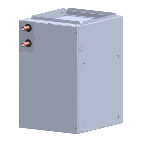
- Page 7 Circulation Pump (for models Hydronic with integrated pump). Coil Circulates hot water between the air handler and tankless Water Inlet water heater/boiler. Hot Water From Water Heater/ Corrosion Resistant Cabinet Boiler into Air Handler (made of heavy gauge galvanized steel) 120V Power Supply Water Outlet Knockout Access Port...
- Page 8 Example Vertical (Upflow with SUPPLY Side Return) Configuration (Air Flows Out) Supply Ductwork Rinnai Tankless Water Heater or Boiler Thermostat A call for heat from the thermostat activates the air handler Water Inlet Water Outlet Hot Water From RETURN Front...
- Page 9 • Multiple air handlers configured for supported on the bottom only and set on installation with a single Rinnai solid floor or a field-supplied supporting tankless water heater or boiler is frame.
- Page 10 24V AC isolation valve control Certifications ETL Listed Reference tables in sections 3.8.4 and 3.8.5 for specific BTU output. Rinnai products are continually being updated and improved; therefore, specifications are subject to change without prior notice. Hydronic Air Handler Installation and Operation Manual...
- Page 11 24V AC isolation valve control Certifications ETL Listed Reference tables in sections 3.8.4 and 3.8.5 for specific BTU output. Rinnai products are continually being updated and improved; therefore, specifications are subject to change without prior notice. Hydronic Air Handler Installation and Operation Manual...
- Page 12 Domestic hot water recirculation operates between calls for heat to ensure a balance of comfort for HVAC heating and domestic hot water. If pairing a Rinnai Hydronic Air Handler with a tankless water heater for domestic hot water recirculation capabilities, Rinnai recommends the following: •...
- Page 13 Blower Speed (Btu/hr) Air Handler Entering Water Model Temperature Tankless water Medium High heaters must have a 120°F 21,000 23,000 24,000 minimum input rate AH083CP 140°F* 29,000 31,000* 34,000 of 160,000 Btu/hr. 160°F 37,000 40,000 43,000 120°F 22,000 25,000 27,000 AH084CP 140°F*...
- Page 14 • Blower Speed (Btu/hr) * Bold text Air Handler Entering Water is default Model Temperature Medium High setting 120°F 21,000 23,000 25,000 AH083P 140°F* 29,000 32,000* 35,000 160°F 38,000 42,000 45,000 120°F 23,000 25,000 27,000 AH084P 140°F* 32,000 35,000* 38,000 160°F 41,000 46,000...
-
Page 15: Right Side
Measurements: in. (mm) Hydronic Air Handler Models NOTE • AH083CP • AH084CP • AH125CP • AH166CP • AH206CP • CP = Models with Internal • AH083P • AH084P • AH125P • AH166P • AH206P Circulation Pump • P = Models without Internal 17.5 (445) - Page 16 Universal Air Handler Rack Assembly Part # Universal rack assembly that mounts to the Rinnai Tankless Water Heater or Boiler for simple installation with the hydronic air handler. Works with all Rinnai AH Series Hydronic Air Handler models. AHRACK-1 Includes hardware for mounting the tankless water heater or boiler to the air handler rack assembly, and hardware for assembling the rack.
- Page 17 10 MFD Capacitor 605000035 12.5 MFD Capacitor 605000036 5 6 Pin Wire Harness 605000037 6 Rinnai Wiring Harness 605000038 7 Door Switch 605000039 Blower Motor 1/3 HP, 120 Volt, 60 Hz. 605000040 Blower Motor 1/2 HP, 120 Volt, 60 Hz.
- Page 18 When choosing an installation location, you must Carefully unpack the air handler. If the unit is ensure proper clearances will be met; the damaged, contact your local dealer/distributor. Do not attempt to use the air handler if it installation environment; water quality; and the appears damaged.
- Page 19 Air Handler Models Minimum Opening Area 0 in. • AH083P/AH083CP 320 square inches (0.206 square meters) • AH084P/AH084CP • AH125P/AH125CP 360 square inches (0.23 square meters) 450 square inches •...
- Page 20 • It is recommended that a trained and qualified as to allow free access to the air handler/ control compartment. professional who has attended a Rinnai installation training class complete your • The air handler and its complementing installation.
- Page 21 • Install ductwork in accordance with NFPA WARNING 90B and any local codes. • Install the conditioned air plenum, ducts Before installing or servicing the air handler, and air filters (not provided) in accordance turn off power to unit. There may be more with NFPA 90B Standard for the than one disconnect switch.
-
Page 22: Electrical Shock
• Use copper conductors only. • All field wiring must be done in accordance with National Electrical Code, applicable requirements of UL and local codes, where WARNING applicable. • Electrical wiring, disconnect means and Electrical Shock: over-current protection are to be supplied by •... - Page 23 Air Handler Piping Diagram Before the total hydraulic resistance of a piping circuit can be found, the individual hydraulic • 5.7.2 Rinnai I-Series Boiler and Air resistances of all fittings, valves, or other such Handler Piping Diagram components must be determined. One...
- Page 24 IMPORTANT Read section “4. Installation Preparation” before starting installation steps. Refer to section “4.5 Ductwork Requirements” for complete ductwork installation requirements. 1. Connect the supply air duct to the flange on top of the blower section of the air handler. Refer to the previous section (section “4.
- Page 25 To Domestic Priority Switch Knockout Connect to White and Black Wires (Normally Closed Model AH206P/CP Wiring Configuration) on Rinnai Domestic Priority Switch Right Side Left Side IMPORTANT: If the Domestic Priority Switch is not used in the installation, remove the wiring harness from the PCB. The thermostat “W”...
- Page 26 Cooling Application with Hot Water Heat Thermostat Air Handler Refer to section “4.6 Thermostat Requirements” for complete thermostat installation requirements. 1. Mount the thermostat approximately 5 ft. (1.5 m) from the floor and close to, or in, a Condensing Unit frequently used room, preferably on an inside partitioning wall or a section of wall without pipes or duct work.
- Page 27 Closed (NC) switch that connects to the PC place. Board in the Rinnai tankless water heater or 3. Locate the PC Board in the bottom, right corner of boiler. the water heater.
- Page 28 4. Connect one end of the accessory cable to the accessory port on the PC Board. Connect the other end of the cable to the switch circuit board accessory port. Switch circuit board accessory port PC Board Accessory cable accessory port 5.
- Page 29 5.6.1.2 Wiring Instructions 1. Attach the harness plug from the Domestic Priority Switch (black, white, and red) as described in Table 1 (located on next page). 2. Install the hydronic air handler per the instructions in the “S-BMS/Air Handler Switch Installation Instructions.”...
-
Page 30: Switch Configuration
5.6.2.2 Wiring Instructions Thermostat Wiring: Using the provided crimp connectors (B in image on previous page), connect the white and black leads of the switch circuit board to the “W” contact on the indoor thermostat and air handler (polarity is not important). See Table 1 below and the wiring diagrams in this section for additional details. - Page 31 IMPORTANT To prevent cold air from being produced, it is recommended to set Parameter 42 to “A - Continuous Run.” See the “Rinnai I-Series Boiler Installation and Operation Manual” for more information. 5.6.3.1 Install Switch Circuit Board 1. Power OFF the boiler by unplugging the power cord or turning off the circuit breaker. The controller on the boiler does not control the electrical power.
- Page 32 5. Attach the air handler/OPU circuit board to the PC Board via double-sided tape. Ensure the circuit board does not make contact with the heat exchanger. 5.6.3.2 Wiring Instructions Table 2: Domestic Priority Configuration 1. Attach the harness plug from the Domestic Priority Switch (black, white, and red) as Switch Required...
- Page 33 2. Open the hot water taps until the air handler turns off. 3. Close the hot water taps. 4. The air handler should turn back on if the thermostat is calling for heat. Air Handler Rinnai Tankless Water Heater or Boiler Air Handler Control Switch...
- Page 34 Domestic Priority Switch Domestic Priority Switch Single Stage Heat Pump with Auxiliary Backup Heat Single Stage A/C Cooling with Single Stage Heating Domestic Priority Switch Single Stage Heat Pump Hydronic Air Handler Installation and Operation Manual...
-
Page 35: Water Outlet
Installation and Operation Manual. • Water connections to the air handler should follow all state and local plumbing codes. 1. Plumb the water out/supply of the Rinnai tankless water Water Inlet heater or boiler to the inlet (top connection) of the air Hot Water From handler. - Page 36 This is not an engineering drawing; it is intended only as a guide and not as a replacement for Optional Low Water professional engineering project drawings. This Cut-Off (LWCO) Outdoor Reset drawing is not intended to describe a complete Sensor system.
- Page 37 Integrated Pump and Check Valve Hot Water Outlets NOTE • Schematic does not apply to Rinnai Tankless Water Heaters equipped with recirculation capability: SE+ Series featuring ThermaCirc360™ models (Super High-Efficiency Plus RUR Models) • Wire solenoid to 24V valve connection on air handler.
- Page 38 Demand Circulation NOTE • Schematic does not apply to Rinnai Tankless Water Heaters equipped with recirculation capability: SE+ Series featuring ThermaCirc360™ models (Super High-Efficiency Plus RUR Models) • Wire solenoid to 24V valve connection on air handler. This is not an engineering drawing; it is intended only as a guide and not as a replacement for professional engineering project drawings.
- Page 39 Flushing the hot water coil prior to start up is The following conditions must be met prior to starting required to remove any residual material from the the air handler. Refer to outdoor condensing unit installation or manufacturing processes as well installation instructions for system start-up instructions as remove any air from the system.
- Page 40 Air Flow Inspection: • For proper cooling operation, the airflow through the indoor coil should be between 350 and 450 CFM per ton of cooling capacity (or 350 – 450 CFM per 12,000 BTU/HR) based on the rating of the outdoor unit. •...
- Page 41 • • When the thermostat calls for heat, the When the thermostat calls for cooling, the thermostat circuit between R and W is thermostat circuit between R and G is completed, activating the hot water completed. circulating pump. • The normally open contacts close, causing •...
- Page 42 The factory-installed freeze protection on all • It is recommended that a trained and qualified air handlers is designed to protect the coil professional who has attended a Rinnai from freezing. The installer must take steps to installation training class perform service to the protect the water piping from freezing.
- Page 43 IMPORTANT Specific blower wire connections may vary by model. Hydronic Air Handler Installation and Operation Manual...
- Page 44 The speed of the air handler is factory default set as per the table to Default Setting Speeds the right. To adjust speed settings, follow the steps below: Model Speed 1. Disconnect power to the air handler. • AH083CP Medium • AH083P WARNING • AH084CP...
- Page 45 Copper NOTE Diameter All values have Fitting 3/4 in. 1 in. been normalized to 90 Degree Elbow 0.75 3/4 in. copper pipe 45 Degree Elbow 0.75 as a baseline. Straight Through Tee 0.135 Side Port Tee 1.35 Reducer Coupling 0.18 Gate Valve 0.25 0.09...
- Page 46 HE Series (V Non-Condensing) BTU Output Maximum Equivalent Blower (Air Handler Models) Pipe Length (ft.) Entering Water Flow Speed Temperature Rate SENSEI™ HE+ and Setting AH083CP AH084CP AH125CP AH166CP AH206CP 18,000 20,000 26,000 31,000 30,000 120°F Medium 19,000 22,000 27,000 32,000 30,000 High...
- Page 47 IMPORTANT If more than 40 equivalent feet of plumbing is needed with the I-Series Boiler, Rinnai recommends the use of hydraulic separation with an external circulation pump. Hydraulic separation uses primary/secondary piping to separate the boiler from the heating system. Hydraulic separator examples include a low loss header (field-supplied), closely spaced tee (field-supplied), or the Primary-Secondary Heating Kit offered by Rinnai (part # 807000212).
Need help?
Do you have a question about the AH125CP and is the answer not in the manual?
Questions and answers