Table of Contents
Advertisement
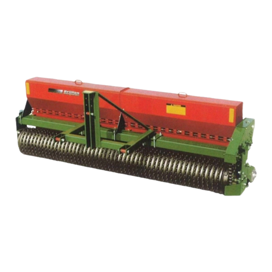
OPERATOR'S MANUAL
TURFMAKER SEEDER
SLP8
8-ft. Pick-up
SSLP8
8-ft. Pick-up
SLP10
10-ft. Pick-up
SSLP10 10-ft. Pick-up
SLP12
12-ft. Pick-up
3 Point Pick Up
SLP10
* Cover illustration may show optional equipment not supplied with standard unit
The standard Turfmaker was designed for seeding grasses and lawn mixtures. It is ideal
for sod and turf producers, or anyone who wishes to seed large areas at precise rates.
Micro-meter adjustment permits precise metering with an infinite range of settings. All
Warning: Standard Turfmaker Seeders have difficulty metering varieties of fine or hard fescues. For mixtures
with fine or hard fescues you must order the Turfmaker II High Capacity Seeders.
8-20-07rev5-28-08
B
rillion
SL8, 10, 12
MODELS AVAILABLE
Pick-Up
Notched Wheels
Smooth Wheels
Notched Wheels
Smooth Wheels
Notched Wheels
pick-up models are designed for Cat. II hitch.
BRILLION
BRILLION, WISCONSIN 54110
www.brillionfarmeq.com
Pull Type
SL10
10-ft. Drawbar Notched Wheels
SSL10
10-ft. Drawbar Smooth Wheels
SL12
12-ft. Drawbar Notched Wheels
SSL12
12-ft. Drawbar Smooth Wheels
Pull Type
SL10
1P342
1P342
Advertisement
Table of Contents

Related Manuals for Brillion SL10 Series


Summary of Contents for Brillion SL10 Series
- Page 1 Cat. II hitch. Warning: Standard Turfmaker Seeders have difficulty metering varieties of fine or hard fescues. For mixtures with fine or hard fescues you must order the Turfmaker II High Capacity Seeders. 8-20-07rev5-28-08 BRILLION 1P342 BRILLION, WISCONSIN 54110 1P342 www.brillionfarmeq.com...
- Page 2 1P342...
- Page 3 Contents Introduction ............................ Location Reference ........................Parts Ordering .......................... Warranty Registration ....................... Safety Information ......................... Safety Information ........................Safety Signs & Locations ......................8, 9 Assembly Instructions ........................10a-27 Special Section: If Seeder is Shipped With Unattached Roller Assemblies .....10a-10h Hydraulic Schematic ........................
- Page 4 1P342...
- Page 5 field operation, unless otherwise stated. Owner Assistance: If customer service or repairs are needed, contact your Brillion dealer. They have trained personnel, parts and service equipment specially designed for Brillion products. Your machine’s parts should only be replaced with Brillion parts.
- Page 6 • Examine safety decals and be sure you have the correct safety decals for the machine. See Safety Sign and Locations in Safety Section for decal locations. • Order replacement decals through your Brillion dealer. • Keep these signs clean so they can be observed readily. It is important to keep these decals cleaned more frequently than the machine.
- Page 7 Safety Important Safety Information Keep Riders Off Machinery • Do not allow anyone to ride on tractor or machine. Riders could be struck by foreign objects or thrown from the machine. • Never allow children to operate equipment. • Keep bystanders away from machine during operation. Transporting Safety •...
- Page 8 Safety Important Safety Information Maintenance Safety * Block machine so it will not roll when working on or under it to prevent injury in case of hydraulic failure or inadvertent lowering by another person. * Do not make adjustments or lubricate machine while it is in motion. * Make sure all moving parts have stopped and all system pressure is relieved.
- Page 9 * When removing and installing wheels, use wheel-handling equipment adequate for weight involved. Use a Safety Chain (Brillion Kit 1K822) * Use a safety chain to help control drawn machinery should it separate from tractor drawbar. * Use a chain with a strength rating equal to or greater than the gross weight of towed machinery, which is 10,100 pounds minimum in accordance with ASAE S338.2...
- Page 10 Safety Signs Safety P/N 2J431 Reflective Amber P/N 9J309 CAUTION List of Pull Type only Cautions MOVING MACHINES CAN CAUSE INJURY. KEEP AWAY! WARNING 1. KEEP AWAY FROM MOVING TRACTORS OR IMPLEMENTS. KEEP OTHERS AWAY. 2. DO NOT RIDE OR ALLOW OTHERS TO RIDE ON TRACTOR OR IMPLEMENT.
- Page 11 Safety Signs Safety P/N 2J430 Reflective Red P/N 8K597 Reflective Red-Orange WARNING Same poisition under Both Covers MOVING PART HAZARD TO PREVENT SERIOUS INJURY FROM MOVING PARTS: • KEEP COVERS CLOSED DURING Right Cover only OPERATION. • DO NOT ALLOW ANYONE TO RIDE OR CLIMB ON MACHINE DURING OPERATION.
- Page 12 SPECIAL ASSEMBLY INSTRUCTIONS If your seeder was shipped with unattached roller assemblies, follow the procedure on pages 10a through 10h. If your rollers were assembled at the factory, go to page 11. 1P342...
- Page 13 Assembly Assem DO NOT WORK ON OR UNDER THIS MACHINE UNLESS SECURELY BLOCKED AND SUPPORTED BY A HOIST OR TRACTOR OR BY OTHER SUFFICIENT MEANS! CAUTION!! --FOR PICK UP SEEDERS STEP 1 • SUPPORT FRAME AND SEEBOX ASSEMBLY with a hoist or by similar means capable of supporting its weight without tipping. Frame &...
- Page 14 Assembly --FOR PULL TYPE SEEDERS STEP 1 • SUPPORT FRAME AND SEEBOX ASSEMBLY with a hoist or by similar means capable of supporting its weight without tipping. STEP 2-a • Attach WHEEL ASSEMBLIES to frame. Frame & Seedbox Assembly RIGHT Pull Type Model Seeder SIDE LEFT SIDE...
- Page 15 Assem STEP 2-b • CENTER DRAWBAR on frame and fasten with 5/8” U-bolts, lockwashers and nuts. •Attach Jack, Hitch and Hose Support. JACK HITCH DRAWBAR U-BOLT, 5/8-11 x 6-11/16 x 5-1/2” HHCS, 5/8-11 x 1-1/2” LOCKWASHER, 5/8 LOCK WASHER, 5/8 NUT, 5/8 NUT, 5/8-11 HHCS, 3/4-10 x 6”...
- Page 16 Assembly ATTACH SEEDER TO TRACTOR. Seeder must be raised with 3 Point Hitch or Hydraulic lift to install roller assemblies. STEP 3 • INSTALL STUB SHAFTS, long shaft on left end, short shaft on right end of front roller assembly. STEP 4 •...
- Page 17 Assembly Assem STEP 6 • POSITION ROLLER ASSEMBLY between frame members and attach flange bearing to frame with grease zerks toward front. Note: Deflectors and transport wheels are not shown in steps 6, 7, and 8 for purposes of clarity. FRONT HHCS, 1/2 x 2”...
- Page 18 Assembly STEP 7 • ATTACH STUB SHAFTS to rear roller assembly, and then add the REAR ARM ASSEMBLIES . Roll rear roller assembly with Rear Arms attached into position behind front roller. FRONT LOCKWASHER, 3/4 HEX NUT, 3/4-10 HHCS, 3/4-10 x 3” (Pick Up Frames) FLAT WASHER, 3/4 HHCS, 1/2-20 x 1-1/4”...
- Page 19 Assem STEP 8 HHCS, 3/4-10 x 3” (Pick Up Frames) HHCS, 3/4-10 X 2” (Drawbar Frames) FLAT WASHER, 3/4 • ATTACH LEFT AND RIGHT REAR ARM assemblies to frame. (Drawing shows left side, right side is the same) Secure to stub shafts with 3/4”...
- Page 20 Assembly ASSEMBLY MACHINE 1P342...
- Page 21 Assembly - Drawbar (Pull-Type) Assem When shipped on factory trucks, seeder comes assembled except for lights, rims, and drawbar or 3 pt. Hitch. HOSE CLAMPS U-bolt, 5/8” x 6-11/16” x 5-1/2” Washer, Lock 5/8 Nut, 5/8-11 1P342...
- Page 22 Assembly - Hydraulic Schematic CYLINDER, 2 1/2 x 6 RESTRICTOR RESTRICTOR ADAPTER ADAPTER ELBOW, 08FJS x 08MJ x45 ELBOW, 08FJS x 08MJ x45 HOSE ASM, 72” (12’Machines) CYLINDER, HOSE ASM, 57” (10’Machines) 2 1/2 x 6 HOSE ASM, 42” (8’Machines) TEE, 08MJx 08MJ x 90 HOSE ASM, 105”...
- Page 23 Assem HHCS, 3/4-10 x 2” STOVER NUT, 3/4” WHEEL BOLT, 1/2-20 X 1” LOCK NUT, 1/2-13 HHCS, 1/2-13 x 3” 1P342...
- Page 24 Assembly - 3-PT. Hitch (Pick-Up) Pick-Up Seeder: 3-Point Hitch Assembly 1. Position three-point hitch weldment on center of frame and secure with four 5/8” x 6-11/16” x 5-1/2” U-bolts, lock washers, and nuts from bag in seed box. 2. Make sure parking pin is engaged before removing bolt in step 3. 3.
- Page 25 Assem WIRING SCHEMATIC 12-ft Seeders Amber Lamp Red Lamp & Light Module Wishbone Straight Ag. Harness Harness Red Lamp To Tractor Amber Lamp Page 15 1P342...
- Page 26 Assembly-Warning Lights HHCS, #8-32 x 3/4 HHCS, 1/4-20 x 1-1/4 Light Module Flat Washer, #8 Nut, 1/4-20 Flange Lock Lock Washer, #8 HHCS, 1/4-20 x 1-1/4 HHCS, Nut, #8-32 Hex Nut, 1/4-20 Flange Lock #8-32 x 3/4 Amber Lamp Red Lamp Amber Lamp HHCS, 3/8 x 1-1/2...
- Page 27 Assem HHCS, 1/4-20 x 1-1/4 Light Module Dual Lamp Dual Lamp Nut, 1/4-20 Flange Lock Bracket, 9K822 (Positon Amber at top; Red faces rear) HHCS, 1/2-13 x 1-1/4 HHCS, 1/4-20 x 1-1/4 Lock Washer, 1/2 Nut, 1/4-20 Flange Lock Nut, 1/2-13 Hex Dual Lamp (Positon Amber at top;...
- Page 28 ASSEMBLE WIRES - 8, 10, & 12-FT Machines: Connect “wishbone” wiring harness ends to connectors on lamp assemblies. Run wishbone harness along seed box, over to hydraulic hose, along hoses or frame, and connect at the plug to the light module. (Wires are fastened to seedbox jor frame with small cable ties and mounting bases with adhesive backs.) •Note: If your seeder is equipped with an electric clutch, install, route and secure electric clutch wire harness with warning light harness..
- Page 29 Assem Page 19 1P342...
- Page 30 Agitator Kit 1. Remove knock-outs for 3/4” flangette bearings. These are located at each end and center of seed box assembly. Hole patterns are as shown below: 3/8” Diameter 2 3/16” Diameter 2. Install bearings and 1/4” thick spacer at left end of seed box. 3.
- Page 31 Agitator Kit Assem HHCS, 5/16-18 x 1 Lock Washer, 5/16 Nut, 5/16-18 Agitator 3rd Seedbox Center Divider HHCS, 1/4-20 x 1-1/2 Shaft Bearing & Lock Washer, 1/2 Flangette Nut, 1/4-20 (Agitators to Shafts) Right HHCS, 5/16-18 x 1 Lock Washer, 5/16 Agitator Center Shaft...
- Page 32 8-20-07rev3-28-08 Page 21a 1P342...
- Page 33 8-20-07rev3-28-08 Page 21b 1P342...
- Page 34 Electronic Acre Meter HHCS, 3/8-16 x 1 1/4” Lock washer, 3/8” Nut, 3/8” ACRE METER BRACKET HHCS, 3/8-16 x 1” MACHINE SCREW, LOCK WASHER, 3/8 #8-32 x 1 1/4” NUT, 3/8-16 FLAT WASHER, #8 ADHESIVE MOUNT BASE PICK UP SWITCH LOCK WASHER, #8 NUT, #8-32 PICK UP...
- Page 35 Assem Top View PICK UP SWITCH CLUTCH SHAFT MAGNET WHEEL Side View PICK UP SWITCH 1/8” Maximum GROUND WIRE 1P342...
- Page 36 ACRE METER KIT TO PROGRAM METER 1. Press function button to scroll to pulses screen. 2. Enter the number of pulses for the model as listed in chart on page 23b using the up or down buttons. 3. Press function button to set pulses. (If screen goes blank before you press the function button, repeat steps 1 &...
- Page 37 ELECTRONIC ACRE METER - QUICK-START SETTINGS SPECIAL NOTES • When meter is set to “count” mode in pulses screen, meter will register only magnetic wheel revolutions. • Meter must be in sleep mode (blank screen) to calculate acres or to count pulses. •...
- Page 38 1P342...
- Page 39 S-Tine Track Remover Assem S-Tine Tire Track Remover (Optional) 1. Attach brackets to frame with u-bolts (1/2” x 4-1/2” centers x 7-1/2” deep), lock washers, and nuts. Note that long ends of brackets are downward. Brackets should be about 53” from center of machine.
- Page 40 Coil Tine Track Remover Assem Coil Tine Track Remover (Optional) [ Cannot be used with Scraper Kit] 1. Assemble the coil tines and the arm weldments to the 1-1/2” diameter x 29” bar. The arm weldments may be placed anywhere along the bar, but it is suggested that they be mounted in the second hole from the right end, and the third hole from the left end.
- Page 41 Speed Up Kit Assem Optional Speed-Up Kit (Optional) Seed rates can be doubled by using a 26-tooth sprocket. Procedure is as follows: 1. Loosen and remove both drive chains. 2. Remove 1/4” x 2 1/4” capscrew, locwasher, and nut from #55 chain (large) sprocket hub on front transmission shaft.
- Page 42 Electric Clutch Kit-- optional The clutch is controlled by a toggle switch mounted to the tractor by a “Velcro” type hook and loop fastener. Clutch characteristics are as follows: 1. Clutch is disengaged when power (12 volts) is applied. If there is a power failure or electrical problem, the seeder will continue to operate, and machine must be raised to stop seeding.
- Page 43 Electric Clutch Kit-- optional Assem (Clutch will make a clicking 1P342...
- Page 44 1P342...
- Page 45 Operation OPERATING MACHINE 8-20-07rev4-3-08 Page 29b 1P342...
- Page 46 Operation Operation Transport Lock (Pull type Seeders Only) To prepare machine for transport: Raise machine fully and pin transport lock in place on each lift cylinder. For field operation: IMPORTANT - Disengage each transport lock and replace pin. (If pin is not installed, transport lock may bounce up and break hydraulic fittings).
- Page 47 Operation Operation Parking Pin (Pick-Up Seeders Only) To prevent machine from tipping backward on frame, disengage parking pin only when seeder is fully attached to tractor. Be sure to observe the following sequence: KLIK PIN PARKING PIN When unhooking seeder: 1.
- Page 48 Operation Operation Seed Rate Adjustment Note: Wrenches for adjustment are stored on a pin at the back of the transmission. IMPORTANT: To prevent damage to seed meters, do not apply excessive force to adjusting nuts. This is especially important when closing meters as seed in flutes can be pinched between cut -off and washer in seed cup.
- Page 49 Operation Operation Transmission Drive Bolt Transmission Drive Bolt A 1/4” x 2-1/4” grade 5 bolt connects the 6 tooth #550 roller chain sprocket to the front transmission shaft. This bolt must be removed for calibration and can also be removed if it is desired to use the seeder as a roller only.
- Page 50 8-20-07rev3-28-08 Page 34 1P342...
- Page 51 1P342...
- Page 52 1P342...
- Page 53 Front Lubrication Front HRS. 1P342...
- Page 54 CLEVIS DRAWBOLT Chain Tension IDLER AXLE BOLT To adjust the transmission chain, first loosen the 5/8” idler axle bolt and then use the clevis draw bolt to obtain about 3/8” - 1/2” of sag. Re-tighten axle bolt. Be careful not to over tighten this chain.
- Page 55 1P342...
- Page 56 Roller Wheels FRONT Occasionally it is necessary to loosen ROLLERS clamp bands and tighten roller wheel assemblies. As nearly as possible, peaks on rear wheels should line up with valleys on front wheels. This requires adjusting both end clamps on CLAMP BANDS the rear axle drum.
- Page 57 Machine Specifications Model Designation SL series grass seeder models are described as follows: Pull type, notched wheels SSL8 Pull type, smooth wheels SLP8 Pick-up type, notched wheels SSLP8 Pick-up type, smooth wheels SL10 Pull type, notched wheels SSL10 Pull type, smooth wheels SLP10 Pick-up type, notched wheels SSLP10 Pick-up type, smooth wheels SL12...
- Page 58 Optional Equipment Approx. Wt. (lbs.) 5K745 Electronic Acre Meter 6J189 15 x 8 lb Wheel for 9.5 L x 15 Tire @24 lbs. ea 9J931 -8ft. Tire Track Remover Kit (includes 6 S-tines with shovels) 9J438 -10ft. (Pick-up seeder requires standard 9J442 long hitch 2K496 -12ft.
- Page 60 Equipment from Landoll Corporation is built to exacting standards ensured by ISO 9001:2008 registration at all Landoll manufacturing facilities. LANDOLL CORPORATION 1900 North Street Marysville, Kansas 66508 (785) 562-5381 800-428-5655 ~ WWW.LANDOLL.COM Copyright 2010. Landoll Corporation "All rights reserved, including the right to reproduce this material or portions thereof in any form"...
Need help?
Do you have a question about the SL10 Series and is the answer not in the manual?
Questions and answers