Table of Contents
Advertisement
Quick Links
PIATTAFORME AEREE SEMOVENTI
SELF-PROPELLED WORK-PLATFORMS
PLATES-FORMES DE TRAVAIL AUTOMOTRICES
SELBSTFAHRENDE HUBARBEITSBÜHNEN
PLATAFORMAS ELEVADORAS AUTOPROPULSADAS
ZELFRIJDENDE HOOGWERKERS
SJÄLVGÅENDE ARBETSPLATTFORMAR
SAMOKRETNE RADNE PLATFORME
ÖNHAJTÁSÚ MUNKAÁLLVÁNYOK
„X_RT" SERIES
X12 RTD X12 RTE X14 RTD X14 RTE
USE AND MAINTENANCE MANUAL
- ENGLISH - ORIGINAL INSTRUCTIONS
AIRO is a division of TIGIEFFE SRL
Via Villasuperiore, 82 - 42045 Luzzara (RE) ITALY -
℡ +39-0522-977365
-
+39-0522-977015
WEB:
www.airo.it
076.20.UEM-EN
2019-07
Advertisement
Table of Contents

Related Manuals for Airo X12 RTD


Summary of Contents for Airo X12 RTD
- Page 1 ÖNHAJTÁSÚ MUNKAÁLLVÁNYOK „X_RT“ SERIES X12 RTD X12 RTE X14 RTD X14 RTE USE AND MAINTENANCE MANUAL - ENGLISH - ORIGINAL INSTRUCTIONS AIRO is a division of TIGIEFFE SRL Via Villasuperiore, 82 - 42045 Luzzara (RE) ITALY - ℡ +39-0522-977365 +39-0522-977015 WEB: www.airo.it...
- Page 2 Revision date Description of revision • 10-2016 First issue • Updated hydraulic diagram: eliminated solenoid valve EV11C 12-2016 • Added final data model X14 RTD • 03-2017 Updated images instructions emergency towing • 11-2017 Updated technical data for models X12 RTE and X14 RTE •...
-
Page 3: Table Of Contents
Tigieffe thanks you for purchasing a product of its range, and invites you to read this manual. Here you can find all the necessary information for a correct use of the purchased machine. Therefore, you are advised to follow the instructions carefully and to read the manual thoroughly. - Page 4 5.1.6.3 Heat engine start button (models” D”, “ED”, “B”, EB”) ......................35 5.1.6.4 Manual horn ..................................35 5.1.6.5 Emergency stop button ..............................35 5.1.6.6 Secondary safety system “S.A.F.E.” (OPTIONAL) ......................35 5.1.6.7 Warning lights ..................................36 5.1.6.8 Enabled control panel green warning light (O) ........................36 5.1.6.9 Sliding platform position green warning light (P - only for machines with sliding platform - NOT AVAILABLE) ....
- Page 5 7.3.4.6 Commissioning / check ..............................62 7.3.4.7 Mix ...................................... 63 7.3.4.8 Micro-filtration ..................................63 7.3.4.9 Disposal ....................................63 7.3.4.10 Topping up ..................................63 7.3.5 Hydraulic filter replacement ..............................64 7.3.5.1 DISCHARGE FILTER ................................. 64 7.3.5.2 Return filter ..................................64 7.3.6 Air purging from oscillating axle locking cylinders ......................... 65 7.3.7 Pressure relief valve adjustment and operation check ......................
-
Page 6: Introduction
This Use and Maintenance Manual provides general instructions concerning the complete range of machines indicated on the cover. Therefore the description of their components, as well as control and safety systems, may include parts not present on Your AIRO-Tigieffe s.r.l. reserves machine since supplied on request or not available. -
Page 7: Further Periodical Checks
1.1.2.2 Further periodical checks Yearly checks are compulsory. In Italy it is necessary that the owner of the Aerial Platform must apply for a periodical check by sending a registered letter to the local competent inspection board (ASL/USL or ARPA or other qualified public or private services) at least twenty days before the expiry of the year from the last check. -
Page 8: Leaving At Height
Do not use the machine for purposes other than those for which it was designed, except after making a request and having obtained written permission in this sense from the manufacturer 1.3.1 Leaving at height The work elevating platforms are not designed by taking into account the risks of the “leaving at height” because the only access position considered is when the platform is completely lowered. -
Page 9: Control Panels
Control panels The machine is equipped with two control panels: On the platform for normal use of the machine. On the chassis is fitted with the emergency controls to lower or stop the platform and the emergency stop button, a key- selector to select the control panel and to start the machine. -
Page 10: Identification
Identification In order to identify the machine, when spare parts and service are required, always mention the information given in the serial number plate. Should this plate (as well as the various stickers applied on the machine) be lost or illegible, it is to be replaced as soon as possible. -
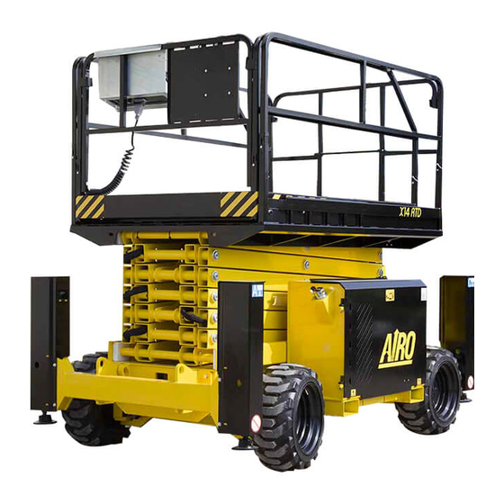
Page 11: Location Of Main Components
Location of main components The picture shows the machine and its own components. 1) Platform control panel 2) Spirit level (standard for models with levelling outriggers; optional for the other models) for visual check of machine levelling 3) Lifting cylinders 4) Lowering control valve 5) Ground control station 6) Electric control unit and inclinometer... -
Page 12: Technical Features Of Standard Machines
2. TECHNICAL FEATURES OF STANDARD MACHINES THE TECHNICAL FEATURES OF THE PRODUCTS IN THE FOLLOWING PAGES CAN BE MODIFIED WITHOUT PRIOR NOTICE Model X12 RTD Dimensions: X12 RTD Maximum working height - STANDARD 12.15 39 ‘8” Maximum working height - WITH LEVELLING OUTRIGGERS (OPTIONAL) 12.45 40 ‘8”... - Page 13 Diesel drive power Diesel engine type YANMAR YANMAR 3TNV76 3TNV76 Motor power 17 kW Starter battery V/Ah 12V / 12V / 100Ah V/Ah 100Ah Diesel oil tank capacity (*) In some cases different limits can be fixed. It is recommended to comply with the data shown on the machine plate. ( ** ) me = m –...
-
Page 14: Model X12 Rte
Model X12 RTE Dimensions: X12 RTE Maximum working height - STANDARD 12.15 39 ‘8” Maximum working height - WITH LEVELLING OUTRIGGERS (OPTIONAL) 12.45 40 ‘8” Max. platform height - STANDARD 10.15 33 ‘3” Max. platform height - WITH LEVELLING OUTRIGGERS (OPTIONAL) 10.45 34 ‘2”... - Page 15 (*) In some cases different limits can be fixed. It is recommended to comply with the data shown on the machine plate. ( ** ) me = m – (n x 80) (***) Wind speeds higher or equal to 12.5 m/s indicate that the machines can also be used outdoors; Wind speeds equal to 0 m/s indicate that the machines can be used INDOORS ONLY.
-
Page 16: Model X14 Rtd
Model X14 RTD Dimensions: X14 RTD Maximum working height - STANDARD 45 ‘9” Maximum working height - WITH LEVELLING OUTRIGGERS (OPTIONAL) 14.3 46.9” Max. platform height - STANDARD 39 ‘3” Max. platform height - WITH LEVELLING OUTRIGGERS (OPTIONAL) 12.3 40 ‘3” Ground clearance 11”... - Page 17 Diesel drive power Diesel engine type YANMAR YANMAR 3TNV76 3TNV76 Motor power 17 Kw Starter battery V/Ah 12V / V/Ah 12V / 100Ah 100Ah Diesel oil tank capacity (*) In some cases different limits can be fixed. It is recommended to comply with the data shown on the machine plate. ( ** ) me = m –...
-
Page 18: Model X14 Rte
Model X14 RTE Dimensions: X14 RTE Maximum working height - STANDARD 45 ‘9” Maximum working height - WITH LEVELLING OUTRIGGERS (OPTIONAL) 14.3 46.9” Max. platform height - STANDARD 39 ‘3” Max. platform height - WITH LEVELLING OUTRIGGERS (OPTIONAL) 12.3 40 ‘3” Ground clearance 11”... - Page 19 (*) In some cases different limits can be fixed. It is recommended to comply with the data shown on the machine plate. ( ** ) me = m – (n x 80) (***) Wind speeds higher or equal to 12.5 m/s indicate that the machines can also be used outdoors; Wind speeds equal to 0 m/s indicate that the machines can be used INDOORS ONLY.
-
Page 20: Vibrations And Noise
Vibrations and noise Noise tests have been carried out under the most unfavourable conditions to study the effects on the operator. The level of acoustic pressure weighed (A) at work places does not exceed 82dB(A) for each electrical models. For all diesel engine models, the level of acoustic pressure weighed (A) at work places does not exceed 110dB(A). As to vibrations in ordinary working conditions: •... -
Page 21: Safety Precautions
3. SAFETY PRECAUTIONS Personal protective equipment (PPE) Always wear personal protective equipment according to current regulations concerning industrial health and safety (in particular, hard COMPULSORY) hat and safety shoes are It is the operator or safety manager’s responsibility to choose the personal protective equipment (PPE) depending on the activity to be carried out. -
Page 22: Use Instructions
Use instructions 3.3.1 General The electric and hydraulic circuits are provided with safety devices, calibrated and sealed by the manufacturer: DO NOT TAMPER WITH AND MODIFY THE CALIBRATION OF ANY COMPONENT OF THE ELECTRIC AND HYDRAULIC SYSTEMS. The machine must be used only in areas well lit up, checking that the ground is flat and firm. The machine may not be used if the lighting conditions are not sufficient. - Page 23 Check that in the operating area there are not obstacles or other dangerous elements. Pay particular attention to the area above the machine during lifting to avoid any crushing and collisions. During operation keep your hands in safety position, the driver has to place them as shown in picture A or B while the transported operator has to keep them as shown in picture C.
-
Page 24: Operating Procedures
3.3.3 Operating procedures The machine is equipped with an inclination control system disabling lifting in case of unstable positioning. Working operations can be resumed only after placing the machine in a steady position. Should the audible device and the red light on the platform control panel turn on, the machine is not correctly positioned (see paragraphs relevant to “General use instructions”... -
Page 25: Wind Speed According To Beaufort Scale
3.3.4 Wind speed according to BEAUFORT SCALE You can use the table below for a simple assessment of the wind speed. We remember that the max. limit for each machine model is indicated in the table TECHNICAL FEATURES OF STANDARD MACHINES. The machines for which the max. -
Page 26: Pressure Of The Machine On Ground And Load-Bearing Capacity Of Ground
3.3.5 Pressure of the machine on ground and load-bearing capacity of ground Before using the machine, the operator must make sure the floor is suitable for withstanding the specific loads and pressures on the ground with a certain safety margin. The following chart provides the parameters in play and two examples of calculation of the average pressure on the ground below the machine and max pressure underneath the wheels or outriggers (p1 and p2). -
Page 27: High-Tension Lines
The table below shows the load-bearing capacity of the ground split up by ground type. Refer to the data contained in the specific tables of each model (chapter 2, TECHNICAL FEATURES OF STANDARD MACHINES) to obtain the figure relating to the max pressure on the ground caused by the single wheel. Using the machine is forbidden if the max pressure on the ground per wheel is above the load-bearing capacity of the specific type of ground on which the machine is to be used. -
Page 28: Installation And Preliminary Checks
4. INSTALLATION AND PRELIMINARY CHECKS The machine is supplied completely assembled, therefore it can perform all functions in safety as provided for by the manufacturer. No preliminary operation is required. To unload the machine, follow the instructions in chapter “Handling and carrying”. Place the machine on a sturdy enough surface (see paragraph 3.3.5 ) and with a gradient below max allowed gradient (see technical characteristics “Stability limits”) Becoming acquainted with the machine... -
Page 29: Use Instructions
5. USE INSTRUCTIONS Before using the machine read this chapter thoroughly. WARNING! Follow exclusively the instructions given in the next paragraphs and the safety rules described both hereafter and in the previous paragraphs. Read the next paragraphs carefully in order to properly understand the on/off procedures as well as all operations and their correct use. - Page 30 ZD) Dead-man button ZE) Secondary safety system “S.A.F.E.” button (optional) A-B-C-D-E Drive, lifting and (optional) platform extension/retraction operations are controlled by the proportional joystick controls ; it is To avoid sudden shakes during movements, it is advisable therefore possible to adjust movement speed by means of the relative controls. to operate the proportional joystick controls gradually.
-
Page 31: Drive And Steering
5.1.1 Drive and steering Before carrying out any displacement operation, verify that no people are in proximity of the machine and in any case proceed with the utmost caution. IT IS FORBIDDEN to drive the machine when the platform is lifted unless the chassis is flat and steady with no holes and steps. -
Page 32: Drive With Operator On The Ground
5.1.2 Drive with operator on the ground If drive operations are to be carried out not from the preset control panel on the platform (e.g. transit through doors where the machine height is too high) you can proceed as follows: Lower the machine completely. -
Page 33: Manual Extension Of The Platform
5.1.4 Manual extension of the platform The extension of the mobile platform is carried out manually. To extend the mobile platform (Figure Press lock pedal Manually push the platform from the inclined part of the rails while holding down pedal Release pedal close to one of the provided slots depending on the extension you wish to achieve. -
Page 34: Levelling Outriggers Manual Control(Optional)
5.1.5.2 Levelling outriggers manual control(OPTIONAL) The machine can be supplied with an optional automatic levelling system. The system has two operating modes: manual mode (see previous paragraph) automatic mode AUTOMATIC LEVELLING The control system will independently control the levelling set the control lever downwards. -
Page 35: Heat Engine Start Button (Models" D", "Ed", "B", Eb")
5.1.6.3 Heat engine start button (models” D”, “ED”, “B”, EB”) It starts the heat engine (Diesel or Petrol) on dual-powered models (ED or EB) and on thermal-powered models (D or B). With THERMIC selector in position operating the switch START position it enables starting. -
Page 36: Warning Lights
5.1.6.7 Warning lights Fig. 7 5.1.6.8 Enabled control panel green warning light (O) On with flashing light If the platform control panel has been selected and this light flashes the controls when the machine is turned on. are not enabled because the dead-man button was not pressed or more than 5 seconds went by since its release and no operation was performed. -
Page 37: Danger Red Warning Light (S)
5.1.6.12 Danger red warning light (S) It flashes quickly for 4 seconds together with the audible alarm at the machine start-up in case of fault during safety test on controls (pedal, joystick control, switches, etc.) during machine start-up. It is lit up steady together with the audible alarm (just in case of lifted platform) when the chassis inclination exceeds the allowed value. -
Page 38: Ground Control Panel
Ground control panel The ground control panel is located on the chassis (see paragraph "Location of main components") and is used to: Turn the machine on/off. Select the control panel (ground or platform). Operate the platform in emergency cases. Display some operation parameters (working hours; Diesel engine operational faults; battery charger operation; etc.). IT IS FORBIDDEN To use the ground control panel as a workstation when personnel is on the platform. -
Page 39: On-Off Key And Control Panel Selector (A)
5.2.1 On-off key and control panel selector (A) The on-off key located on the ground control panel is used to: turn ON the machine by selecting one of the two control panels: Platform controls enabled with locking key switch set to “platform” symbol. Stable key position with possibility to extract the key. -
Page 40: User Interface Display (E)
5.2.5 User interface display (E) The multifunction display for machine/user interface is used to: Display the operation parameters of the machine during normal functioning or in the event of a fault; Working hours of Diesel engine (when Diesel power is selected the working hours are displayed in the format HOURS: MINUTES and final letter D). -
Page 41: Platform Access
Platform access The “access position” is the only one from which loading or unloading of persons and materials is allowed. The “access position” to the work platform is the completely lowered configuration. To get on the platform: Get on the ladder hanging on to the rungs, the ladder side rails or the entry guard rails. -
Page 42: Heat Engine Start-Up
5.4.1 Heat engine start-up By turning the starter key on the platform control panel: To “0” position the Diesel engine stops (models “D” and “ED”). To “3 sec” position the plugs pre-heating takes place (only engines with plugs) (models “D” and “ED”). To “Start”... -
Page 43: Starting The 380V Three-Phase Electric Pump (Optional)
5.4.3 Starting the 380V three-phase electric pump (OPTIONAL) Diesel-powered models can be equipped, on request, with a 380V three-phase electric pump. To start the three-phase electrical pump: Insert the 380 V plug of the power cable into socket (A) on the chassis. Set the switches (C) shown in figure to ON position. -
Page 44: Machine Stop
Machine stop 5.5.1 Normal stop During the normal stop of the machine, if you release the controls, the operation is stopped. Stop occurs within a time limit set in the factory, which guarantees smooth braking. 5.5.2 Emergency stop button Should it be necessary, the operator may immediately stop all machine functions on both platform and ground control panel. On the platform control panel: Press the emergency stop button on the control panel and the machine is turned off. -
Page 45: Stopping The 380V Three-Phase Or 230V Single-Phase Electrical Pump (Optional)
5.5.4 Stopping the 380V three-phase or 230V single-phase electrical pump (optional) To stop the electrical pump (optional): On the platform control panel: Press the stop button. Otherwise, press the emergency stop button. On the ground control panel: Press the emergency stop button. Manual emergency lowering This function is to be used only in emergency situations, when no motive power is available. -
Page 46: Manual Emergency Lowering: Optional Control With Manual Pump
5.6.1 Manual emergency lowering: Optional control with manual pump Fig. 13 On request the machines can be equipped with double emergency lowering from the ground and the platform, as shown in the pictures above. The manual pump on the platform is protected by a metal protection fixed to the platform deck through two threaded knobs. -
Page 47: Socket For Electric Tool Connection (Optional)
Socket for electric tool connection (optional) The work platform can be equipped with a socket (230V Ac) enabling the operator to connect the electric tools necessary to carry out his operations. To activate the electric line (see pictures above) introduce a cable into the plug connected to the 230V AC 50 Hz mains, with all protections according to the current standards in force. -
Page 48: End Of Work
End of work After stopping the machine according to the instructions given in the previous paragraphs: Always set the machine to rest position (platform completely lowered). Press the emergency Stop button on the ground control panel. Remove the keys from the control panel to prevent unauthorized people from using the machine. Recharge the battery according to the instructions given in section "Maintenance"... -
Page 49: Handling And Carrying
6. HANDLING AND CARRYING Handling To handle the machine in normal operating conditions follow the instructions given in chapter "USE INSTRUCTIONS" under paragraph "Drive and steering”. When platform is completely lowered (or within a given height according to specific needs and further to checks) the machine can be handled (i.e. -
Page 50: Carrying
Carrying In order to carry the machine to the various working sites, follow the instructions given below. Considering the large dimensions of some models, before carrying, it is recommended to inquire about the overall dimension limits for road transport in force in your country. Before carrying the machine, turn it off and remove the keys from the control panels. - Page 51 After placing the machine onto the carrying vehicle, fasten it by means of the same holes used for lifting. DO NOT fix the machine to To avoid breaking the platform overload controller, thus causing the machine to stop, the vehicle base by tying the platform (any model) or the last lifting boom. Before carrying the machine check the stability grade.
-
Page 52: Fold-Down Rails
6.2.1 Fold-down rails The machines is fitted with rails folding down to the inside of the platform. Folding down the rails it is possible to reduce the height of the machine for: Transport. Passage through lowered areas (e.g. doors) To fold down the rails follow this procedure: 1) Extend the mobile platform and lock it in the indicated position. - Page 53 RAILS FOLDING-DOWN SEQUENCE Use and Maintenance Manual - X_RT Series Page 53...
-
Page 54: Emergency Towing Of The Machine
Emergency towing of the machine In the event of a fault, carry out the following operations to Type 1: tow the machine: Hook the machine to the provided holes (the same used for lifting – see previous pictures). Screw knob completely on the hydraulic block. -
Page 55: Maintenance
The maintenance operations described below refer to a machine with ordinary working use. In case of difficult conditions of use (extreme temperatures, corrosive environments, etc.) or following long machine inactivity, it will be necessary to contact the AIRO assistance service to change the intervention schedule. -
Page 56: Safety Lock For Maintenance Operations
Safety lock for maintenance operations Before carrying out any maintenance or repairs to it, activate the lifting structure locking system. Watch the pictures aside to understand how the lifting locking structure works before carrying out any maintenance or repairs to it. Unscrew knobs completely (on both sides of the lifting structure). -
Page 57: General Maintenance
General maintenance Below are listed the main maintenance jobs to be done and the relevant schedule (the machine features an hour meter). Operation Frequency Screw tightening (see paragraph "Various adjustments") After the first 10 working hours Oil level check in hydraulic tank After the first 10 working hours Check of the battery state (charge and liquid level) Every day... -
Page 58: Various Adjustments
7.3.1 Various adjustments Check the conditions of the following components and, if necessary, tighten after the first 10 working hours and, afterwards, at least once a year: 1) Wheels nuts and wheels nuts blocking pins 2) Traction motor fixing screws 3) Steering cylinder fixing screws 4) Platform and guard rails fixing screws 5) Hydraulic fittings... -
Page 59: Greasing
7.3.2 Greasing Grease all articulated joints equipped with greaser (or predisposition for greaser) at least every month. At least once a month, using a spatula or a brush, lubricate the sliding guides of the: a) Sliding blocks/rolls of the extensible structure on the chassis. -
Page 60: Diesel Motor
7.3.3 Diesel Motor For all maintenance operations relating to the Diesel engine refer to the manual of instructions of the manufacturer of the engine that is supplied with the machine. The diesel engine ( ) is housed on a removable support ( ) to facilitate access to accessories/devices located in the rear area. -
Page 61: Hydraulic Circuit Oil Level Check And Change
7.3.4 Hydraulic circuit oil level check and change Check the level periodically by means of the provided indicator (detail A in the picture aside) and make sure that the level always lies If necessary top up until max. between the max. and min. values. level is reached. -
Page 62: Biodegradable Hydraulic Oil (Optional)
soap and rinse thoroughly. Contact with eyes, especially with electrolytes, is also dangerous; rinse with water thoroughly and call the doctor. 7.3.4.1 Biodegradable hydraulic oil (Optional) At the request of the customer, the machines can be supplied with biodegradable hydraulic oil compatible with the environment. Biodegradable hydraulic oil is completely synthetic, without zinc, non-polluting and highly efficient with saturated ester base, combined with special additives. -
Page 63: Mix
The samples must be sent to the “bio” oil supplier. For more dispatch details, contact Your nearest distributor. Copies of the analysis report must be kept in the check register. This is mandatory. 7.3.4.7 Mix Mixtures with other biodegradable oils are not allowed. The remaining amount of mineral oil must not exceed 5% of total filling quantity as long as the mineral oil is suitable for the same use. -
Page 64: Hydraulic Filter Replacement
7.3.5 Hydraulic filter replacement 7.3.5.1 DISCHARGE FILTER The discharge filters (N.2) are represented in the picture to the side. The filtering cartridge should be replaced at least every two years. To replace the filtering cartridge: Stop the machine by pressing the emergency stop button on the ground control unit. -
Page 65: Air Purging From Oscillating Axle Locking Cylinders
7.3.6 Air purging from oscillating axle locking cylinders Once drive has been stopped, the axle locking cylinders are locked in position thus increasing the machine stability. Check that no air is present inside the oscillating axle cylinders every year. order to carry out this check it is necessary to raise the front wheels off the ground (for machines equipped with levelling outriggers is sufficient to lower the levelling outriggers) and verify that the axle remains in position when stressed. -
Page 66: Pressure Relief Valve Adjustment And Operation Check
7.3.7 Pressure relief valve adjustment and operation check The pressure relief valves (A -B) control the maximum pressure of the hydraulic circuit. Normally, this valve does not require any adjustment, since it is calibrated at the factory before the machine is delivered. The pressure relief valve must be calibrated in the following cases: in case of replacement of the hydraulic block In case of replacement of the pressure relief valve only... -
Page 67: Lifting Circuit Pressure Relief Valve Adjustment
7.3.8 Lifting circuit pressure relief valve adjustment The self-propelled aerial platforms, X_RT series have a pressure relief valve on the lifting circuit C to avoid dangerous overpressure values. Normally, this valve does not require any adjustment, since it is calibrated at the factory before the machine is delivered. Calibration is required: in case of replacement of the hydraulic block in case of replacement of the pressure relief valve only. -
Page 68: Braking System Efficiency Check
7.3.9 Braking system efficiency check These valves check the minimum operating pressure during drive (in both running directions) and affect the dynamic braking and the drive speed. Normally, these valves do not require any adjustment, since they are calibrated at the factory before the machine is delivered. The braking valves stop the machine when the drive controls are released. -
Page 69: Extendable Platform Clearance Adjustment
7.3.10 Extendable platform clearance adjustment Every year check the clearance of the nylon counter- pressure rolls of the slide-out extension deck. To adjust: Unscrew dowel A. Screw in the adjusting dowel B unscrewing or screwing depending on the case. Once the desired clearance is achieved, reposition dowel A. -
Page 70: Inclinometer Operation Check
7.3.11 Inclinometer operation check WARNING! Usually the inclinometer does not need to be adjusted unless the electronic control unit is replaced. The equipment necessary for the replacement and adjustment of this component is such that these operations should be carried out by skilled personnel. AS THIS OPERATION IS VERY IMPORTANT IT IS TO BE CARRIED OUT BY SKILLED TECHNICIANS ONLY. -
Page 71: Operation Check And Adjustment Of Platform Overload Controller
7.3.12 Operation check and adjustment of platform overload controller The AIRO self-propelled aerial platforms, X_RT series, are equipped with a sophisticated platform overload controller. Normally the overload controller does not require any adjustments, since it is calibrated in the factory before the machine is delivered. -
Page 72: Overload Controller By-Pass - Only For Emergency Operations
7.3.13 Overload controller by-pass – ONLY FOR EMERGENCY OPERATIONS In case of fault and impossibility to calibrate the device, a by-pass of the system is possible by means of locking key switch (A) under the control panel. Keep the locking key switch active for 5 seconds and release to get the BY-PASS condition. -
Page 73: Operation Check Of Safety Microswitches
7.3.14 Operation check of safety microswitches Some microswitches are placed in strategic positions to check the different configurations of the machine and activate safety functions. Their activation implies visual indication through the warning lights located on the platform control panel (see relevant chapter). -
Page 74: Stp1-Stp2-Stp3-Stp4 Microswitches (Machines With Levelling Outriggers)
7.3.14.5 STP1-STP2-STP3-STP4 Microswitches (machines with levelling outriggers) The STP1-STP2-STP3-STP4 microswitches on the chassis near the levelling outriggers check the position of the pads of the levelling outriggers. With all pads not resting on the ground (the machine rests on its wheels) all STP… microswitches are not activated and: Lifting can be controlled (unless other alarms) –... -
Page 75: Dead-Man Button Efficiency Check
7.3.15 Dead-man button efficiency check The platform dead-man button is for enabling the operation controls of the machine from the platform control station. Check operation at least once a year. WARNING! IN CASE OF NO OPERATION, CONTACT THE AFTER-SALES SERVICE To check the dead-man BUTTON: Move the drive joystick forward and backward in sequence, WITHOUT PRESSING THE DEAD-MAN BUTTON Check that the machine does not perform any movement... -
Page 76: Starter Battery
Starter battery The battery is one of the most important elements of the machine. It is recommended to keep it in an efficient condition to increase its useful life, to avoid faults and to reduce the management costs of the machine. The starter battery is for: Powering the machine control circuits. -
Page 77: Drive" Battery For Models "Rte" And "Rted
“DRIVE” battery for models “RTE” and “RTED” The battery is one of the most important elements of the machine. It is recommended to keep it in an efficient condition to increase its useful life, to avoid faults and to reduce the management costs of the machine. 7.5.1 General instructions for DRIVE battery In case of new batteries do not wait for the flat battery warning before recharging;... -
Page 78: Drive Battery Recharge
7.5.3 DRIVE battery recharge WARNING! EXPLOSIVE gas is originated during battery charging process. Therefore, charging must take place in airy rooms where no risks of fire and explosion exist and in the presence of fire extinguishers. Connect the battery charger to the power mains having all protections according to the current standards in force and with the following features: Power voltage 230V ±... -
Page 79: Battery Charger: Fault Report
WARNING DESCRIPTION flashing for a few seconds Battery charger self-diagnostic phase Red led on Indicates the first and second charging phase Yellow led on Indicates the equalization of the charging phase Green led on Indicates that charging is over; buffer charge active With the battery charger ON, the machine is automatically off. -
Page 80: Battery Replacement
7.5.5 Battery replacement Replace the old batteries only with models of the same voltage, capacity, dimensions and mass. Batteries must be approved by the manufacturer. Do not dispose of batteries in the environment after replacement. Comply with the current local standards. AS THIS OPERATION IS VERY IMPORTANT IT IS TO BE CARRIED OUT BY SPECIALIZED TECHNICIANS ONLY. -
Page 81: Marks And Certifications
8 . MARKS AND CERTIFICATIONS The models of self-propelled aerial platform described in this manual were subject to the CE type test according to the Directive 2006/42/EC. The certification was issued by: ICE Spa Via Garibaldi, 20 40011 Anzola Emilia – BO (Italy) Test carrying out is shown by the above plate with CE mark applied on the machine and by the declaration of conformity enclosed in this user manual. -
Page 82: Plates And Stickers
LIFTING POINT STICKER 001.10.076 FEET DANGER STICKER 001.10.098 STOP STICKER I-D-F-NL-B-GB 001.10.150 OIL TYPE STICKER “46” I_D_F_NL_B_G_PL 001.10.175 AIRO PRE-SPACED YELLOW STICKER .530X265 001.10.180 NEXT CHECK STICKER 001.10.243 “MAX. LOAD PER WHEEL" STICKER 001.10.261 NO STOPPING STICKER SCISSORS SIMBOL 010.10.010 YELLOW-BLACK LINE STICKER >150X300... - Page 83 Use and Maintenance Manual - X_RT Series Page 83...
-
Page 84: Check Register
10. CHECK REGISTER The check register is released to the user of the platform in conformance with Attachment 1 of Directive 2006/42/EC. This register is to be considered an integral part of the equipment and must accompany the machine for its entire life until its final disposal. - Page 85 REQUIRED PERIODIC INSPECTIONS BY THE REGULATORY AGENCY Date Observations Signature + Stamp Use and Maintenance Manual - X_RT Series Page 85...
- Page 86 REQUIRED PERIODIC INSPECTIONS BY THE OWNER STRUCTURAL CHECK DESCRIPTION OF OPERATIONS TO BE PERFORMED Check the integrity of the guardrails; the harness anchoring points; state VISUAL CHECK of the lifting structure; any access ladders; rust; state of the tyres; oil leaks;...
- Page 87 REQUIRED PERIODIC INSPECTIONS BY THE OWNER STRUCTURAL CHECK DESCRIPTION OF OPERATIONS TO BE PERFORMED VARIOUS ADJUSTMENTS See chapter 7.3.1 DATE REMARKS SIGNATURE + STAMP 1st YEAR 2nd YEAR 3rd YEAR 4th YEAR 5th YEAR 6th YEAR 7th YEAR 8th YEAR 9th YEAR 10th YEAR See chapter 7.3.2...
- Page 88 REQUIRED PERIODIC INSPECTIONS BY THE OWNER CHECK DESCRIPTION OF OPERATIONS TO BE PERFORMED See chapter 7.3.4 HYDRAULIC TANK OIL LEVEL Monthly operation. It is not necessary to indicate its execution every CHECK month, but at least every year when the other operations are carried out. DATE REMARKS SIGNATURE + STAMP...
- Page 89 REQUIRED PERIODIC INSPECTIONS BY THE OWNER CHECK DESCRIPTION OF OPERATIONS TO BE PERFORMED AIR PURGING FROM OSCILLATING See chapter 7.3.6. AXLE CYLINDERS DATE REMARKS SIGNATURE + STAMP 1st YEAR 2nd YEAR 3rd YEAR 4th YEAR 5th YEAR 6th YEAR 7th YEAR 8th YEAR 9th YEAR 10th YEAR...
- Page 90 REQUIRED PERIODIC INSPECTIONS BY THE OWNER CHECK DESCRIPTION OF OPERATIONS TO BE PERFORMED CALIBRATION CHECK OF LIFTING See chapter 7.3.8 CIRCUIT PRESSURE RELIEF VALVE DATE REMARKS SIGNATURE + STAMP 1st YEAR 2nd YEAR 3rd YEAR 4th YEAR 5th YEAR 6th YEAR 7th YEAR 8th YEAR 9th YEAR...
- Page 91 REQUIRED PERIODIC INSPECTIONS BY THE OWNER CHECK DESCRIPTION OF OPERATIONS TO BE PERFORMED PLATFORM EXTRACTION See chapter 7.3.10 CLEARANCE ADJUSTMENT DATE REMARKS SIGNATURE + STAMP 1st YEAR 2nd YEAR 3rd YEAR 4th YEAR 5th YEAR 6th YEAR 7th YEAR 8th YEAR 9th YEAR 10th YEAR INCLINOMETER OPERATION CHECK See chapter 7.3.11...
- Page 92 REQUIRED PERIODIC INSPECTIONS BY THE OWNER CHECK DESCRIPTION OF OPERATIONS TO BE PERFORMED EFFICIENCY CHECK OF PLATFORM See chapter 7.3.12 OVERLOAD CONTROLLER DATE REMARKS SIGNATURE + STAMP 1st YEAR 2nd YEAR 3rd YEAR 4th YEAR 5th YEAR 6th YEAR 7th YEAR 8th YEAR 9th YEAR 10th YEAR...
- Page 93 REQUIRED PERIODIC INSPECTIONS BY THE OWNER CHECK DESCRIPTION OF OPERATIONS TO BE PERFORMED DEAD MAN See chapter 7.3.15 SYSTEM CHECK DATE REMARKS SIGNATURE + STAMP 1st YEAR 2nd YEAR 3rd YEAR 4th YEAR 5th YEAR 6th YEAR 7th YEAR 8th YEAR 9th YEAR 10th YEAR See chapter 7.4 and 7.5.
- Page 94 REQUIRED PERIODIC INSPECTIONS BY THE OWNER CHECK DESCRIPTION OF OPERATIONS TO BE PERFORMED TOTAL OIL CHANGE IN HYDRAULIC See chapter 7.3.4. TANK DATE REMARKS SIGNATURE + STAMP 2nd YEAR 4th YEAR 6th YEAR 8th YEAR 10th YEAR See Chapter 9. Check the legibility of the aluminium plate on the platform where the main instructions are summarised;...
- Page 95 REQUIRED PERIODIC INSPECTIONS BY THE OWNER CHECK OF EMERGENCY DEVICES DESCRIPTION OF OPERATIONS TO BE PERFORMED MANUAL EMERGENCY LOWERING See chapter 5.6 CHECK DATE REMARKS SIGNATURE + STAMP 1st YEAR 2nd YEAR 3rd YEAR 4th YEAR 5th YEAR 6th YEAR 7th YEAR 8th YEAR 9th YEAR...
- Page 96 COMPANY DATE MODEL SERIAL NUMBER DELIVERY DATE AIRO / Tigieffe S.r.l. SUBSEQUENT TRANSFERS OF OWNERSHIP COMPANY DATE We affirm that, as of the date quoted above, the technical, dimensional and functional features of this machine were in conformance with what was originally required and that any changes have been recorded in this Register.
- Page 97 IMPORTANT BREAKDOWNS DATE DESCRIPTION OF BREAKDOWN SOLUTION SPARE PARTS USED DESCRIPTION CODE QUANTITY SERVICE SAFETY MANAGER DATE DESCRIPTION OF BREAKDOWN SOLUTION SPARE PARTS USED DESCRIPTION CODE QUANTITY SERVICE SAFETY MANAGER Use and Maintenance Manual - X_RT Series Page 97...
- Page 98 IMPORTANT BREAKDOWNS DATE DESCRIPTION OF BREAKDOWN SOLUTION SPARE PARTS USED DESCRIPTION CODE QUANTITY SERVICE SAFETY MANAGER DATE DESCRIPTION OF BREAKDOWN SOLUTION SPARE PARTS USED DESCRIPTION CODE QUANTITY SERVICE SAFETY MANAGER Use and Maintenance Manual - X_RT Series Page 98...
-
Page 99: Declaration Of Conformity Ec Facsimile
11. DECLARATION OF CONFORMITY EC FACSIMILE DICHIARAZIONE CE DI CONFORMITA' - CE DECLARATION OF CONFORMITY - DECLARATION CE DE CONFORMITE' - EG KONFORMITÄTSERKLÄRUNG - DECLARACION CE DE CONFORMIDAD- ЗАЯВЛЕНИЕ О КОНФОРМНОСТИ EC 2006/42/CE Dichiarazione originale Original Declaration Déclaration Originale Originalerklärung Declaración Original Оригинальнaя... - Page 100 DICHIARAZIONE CE DI CONFORMITA' - CE DECLARATION OF CONFORMITY - DECLARATION CE DE CONFORMITE' - EG KONFORMITÄTSERKLÄRUNG - DECLARACION CE DE CONFORMIDAD- ЗАЯВЛЕНИЕ О КОНФОРМНОСТИ EC 2006/42/CE Dichiarazione originale Original Declaration Déclaration Originale Originalerklärung Declaración Original Оригинальнaя декларация Noi - We - Nous - Wir – Nosotros- мы Tigieffe S.r.l.
- Page 101 DICHIARAZIONE CE DI CONFORMITA' - CE DECLARATION OF CONFORMITY - DECLARATION CE DE CONFORMITE' - EG KONFORMITÄTSERKLÄRUNG - DECLARACION CE DE CONFORMIDAD- ЗАЯВЛЕНИЕ О КОНФОРМНОСТИ EC 2006/42/CE Dichiarazione originale Original Declaration Déclaration Originale Originalerklärung Declaración Original Оригинальнaя декларация Noi - We - Nous - Wir – Nosotros- мы Tigieffe S.r.l.
- Page 102 DICHIARAZIONE CE DI CONFORMITA' - CE DECLARATION OF CONFORMITY - DECLARATION CE DE CONFORMITE' - EG KONFORMITÄTSERKLÄRUNG - DECLARACION CE DE CONFORMIDAD- ЗАЯВЛЕНИЕ О КОНФОРМНОСТИ EC 2006/42/CE Dichiarazione originale Original Declaration Déclaration Originale Originalerklärung Declaración Original Оригинальнaя декларация Noi - We - Nous - Wir – Nosotros- мы Tigieffe S.r.l.
-
Page 103: Electric Diagram
12. ELECTRIC DIAGRAM 12.1 ELECTRIC DIAGRAM X12 RTD – X14 RTD Use and Maintenance Manual - X_RT Series Page 103... - Page 104 Use and Maintenance Manual - X_RT Series Page 104...
- Page 105 Use and Maintenance Manual - X_RT Series Page 105...
- Page 106 Use and Maintenance Manual - X_RT Series Page 106...
- Page 107 Use and Maintenance Manual - X_RT Series Page 107...
- Page 108 Use and Maintenance Manual - X_RT Series Page 108...
- Page 109 Use and Maintenance Manual - X_RT Series Page 109...
-
Page 110: Electric Diagram X12 Rte - X14 Rte
12.2 ELECTRIC DIAGRAM X12 RTE – X14 RTE Use and Maintenance Manual - X_RT Series Page 110... - Page 111 Use and Maintenance Manual - X_RT Series Page 111...
- Page 112 Use and Maintenance Manual - X_RT Series Page 112...
- Page 113 Use and Maintenance Manual - X_RT Series Page 113...
- Page 114 Use and Maintenance Manual - X_RT Series Page 114...
- Page 115 Use and Maintenance Manual - X_RT Series Page 115...
- Page 116 Use and Maintenance Manual - X_RT Series Page 116...
-
Page 117: Hydraulic Diagram X12 Rtd - X14 Rtd - X12 Rte - X14 Rte
13. HYDRAULIC DIAGRAM X12 RTD – X14 RTD – X12 RTE – X14 RTE DISCHARGE FILTER TANK HYDRAULIC BLOCK DOUBLE PUMP PRESSURE GAGE CONNECTION DRIVE HYDRAULIC MOTOR LEVELLING JACK HYDRAULIC BLOCK LEVELLING JACK CYLINDER SWING AXLE CYLINDER OSCILLATING AXLE HYDRAULIC BLOCK STEERING CYLINDER LOWERING CONTROL INTEGRATED ASSEMBLY LIFTING CYLINDER... - Page 118 Use and Maintenance Manual - X_RT Series Page 118...
Need help?
Do you have a question about the X12 RTD and is the answer not in the manual?
Questions and answers