
Related Manuals for AGT 5580/3 GP200


Summary of Contents for AGT 5580/3 GP200
- Page 1 AGENT TRADE OWNER’S MANUAL AGT 5580/3 GX200 AGT 5580/3 GX160 AGT 5580/3 GP160 AGT 5580/3 GP200 www.agt.ro...
-
Page 2: Risk Of Hearing Damage
INTRODUCTION TRANSLATION OF ORIGINAL INSTRUCTIONS To correctly use the tiller and prevent accidents, do not start work without having first carefully read this manual. You will find explanations concerning the operation of the various parts plus instructions for necessary checks and relative maintenance. Note: Illustrations and specifications in this manual may vary according to each country’s requirements and are subject to change without notice by the manufacturer. - Page 3 INDEX INTRODUCTION ..........OPERATION AND SAFETY...... EXPLANATION OF SYMBOLS AND SAFETY STOPPING THE ENGINE ......WARNINGS............MAINTENANCE ........SAFETY PRECAUTIONS........TECHNICAL DATA …........ TILLER COMPONENTS…………………………… DECLARATION OF CONFORMITY ……... SCOPE OF DELIVERY……………………………. MAINTENANCE CHART ......ASSEMBLY ............TROUBLE SHOOTING CHART ....STARTING ............
-
Page 4: Explanation Of Symbols And Safety Warnings
EXPLANATION OF SYMBOLS AND SAFETY WARNINGS Read tiller owner’s manual before operating this machine. When the engine is running, do not put hands or feet near the rotating blades. WARNING! - Blades continue to rotate a few seconds after the machine is switched off ... -
Page 5: Safety Precautions
SAFETY PRECAUTIONS WARNING: Exposure to vibrations through prolonged use of gasoline powered hand tools could cause blood vessel or nerve damage in the fingers, hands, and wrists of people prone to circulation disorders or abnormal swellings. Prolonged use in cold weather has been linked to blood vessel damage in otherwise healthy people. - Page 6 engaged. - When using the machine, maintain a safe distance from the rotating blades. This is approximately the same distance as the length of the handlebars. - When operating the machine on steep slopes, the user must ensure that nobody is located within a 20 meters radius of the machine.
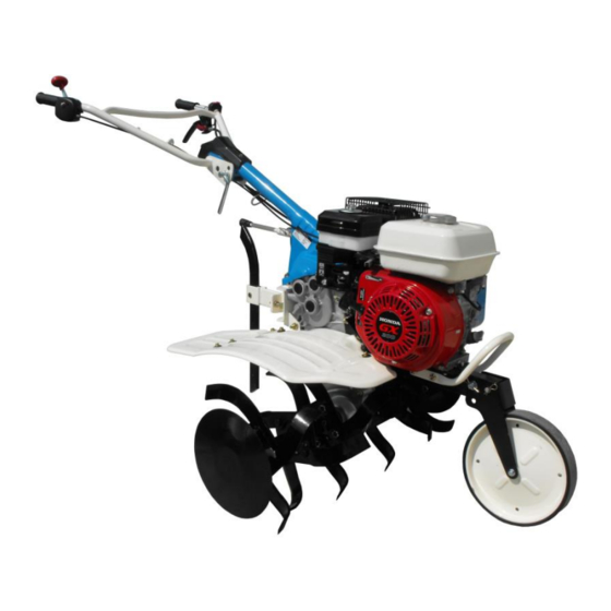
- Page 7 TILLER COMPONENTS 1 – End disc 13 – Gearshift lever 2 – Rotating blade assembly 14 – Air filter 3 – Blade guard 15 – Muffler 4 – Gear box oil dipstick 16 – Fuel tank cap 5 – Recoil starter handle 17 –...
-
Page 8: Scope Of Delivery
SCOPE OF DELIVERY... - Page 9 Housing with motor / gearbox and handlebar (1x) Bag with mounting material Hexagon wrench 10/12 (1x) Hexagon wrench 12/14 (1x) Hexagon wrench 13/16 (1x) Screwdriver (1x) Rubber ring (6x) Fastening pin large with split pin (8x) Fastening pin small with split pin (1x) Wing screw with washer (2x) Hexagon screw with edge (1x) B10 Phillips screw (2x)
- Page 10 ASSEMBLY...
- Page 12 Models with GX160 and GX200 only. Models with GP160 and GP200 only. Models with GP160 and GP200 only. Models with GX160 and GX200 only.
- Page 14 At first check all parts of the device and place them in front of you on the floor. Assembling the front wheel (12) (Fig.3) Attach the support wheel (12) to the frame as shown in figure 3. For this purpose, the two holes (3a + 3b) must be brought into conformity.
- Page 15 Fitting the steering column (E) (Fig. 7-12) To install the steering column (E) proceed as follows: • Loosen the 4 screws (7a) (Fig. 7). • Loosen screw (8a) and remove them (Fig. 8). Attention! Insert the pin (9a) of the steering column (E) into the gear selector lever (22) (see Fig.9).
- Page 16 Plow function (Fig. 28/29/32) Fasten the wheel mountings (I) as shown in fig. 28. • Grease the tool shaft (3g) and pay attention to the alignment of the mounting hole (3i) (Fig. 3) when installing the pneumatic wheels (K). 1. Insert the fastening pins large (B6) into the openings and secure them with the split pins. 2.
-
Page 17: Oil Filler Cap
Check the transmission oil level. Running the transmission with low oil level can cause transmission damage. This type of damage is not covered by the Warranty. OIL FILLER CAP Check the transmission oil level with the engine stopped and in a level position. 1. -
Page 18: Starting The Engine
WARNING: Always wear protective gloves when performing maintenance. Refueling (Do Not Smoke!) This product is powered by a 4-stroke engine. Store unleaded gasoline in a clean container approved for gasoline. RECOMMENDED FUEL: THIS ENGINE IS CERTIFIED TO OPERATE ON UNLEADED GASOLINE INTENDED FOR AUTOMOTIVE USE WITH AN OCTANE RATING OF 89 ([R + M] / 2) OR HIGHER Never use stale or contaminated gasoline or an oil/gasoline mixture. -
Page 19: Changing Gear
closed WARNING – FOR FURTHER INFORMATION ON THE START-UP PROCEDURE, READ THE ENGINE MANUAL CAREFULLY. CONTROLS To activate the drive control lever (B, Fig.42), first disengage it by pressing the safety lever (A). CAUTION – To prevent premature wear of the drive belts, pull the control lever all the way. CHANGING GEAR WARNING! –... -
Page 20: Operation And Safety
High Altitude Operation At high altitude, the standard carburetor air-fuel mixture will be excessively rich. Performance will decrease, and fuel consumption will increase. High altitude performance can be improved by specific modifications to the carburetor. If you always operate the engine at altitudes higher than 1.500 m above sea level, have your authorized dealer perform these carburetor modifications. -
Page 21: Prohibited Use
WARNING - The rotation of the blades causes the motorhoe to move forwards. WARNING - Move the transporting wheels out of the way (upwards) when using the machine. PROHIBITED USE - Never load the blade by putting a ballast weight on it. - Never pull the motorhoe over hard surfaces or uneven surfaces such as paving or steps. -
Page 22: Maintenance
MAINTENANCE CAREFULLY READ THE ENGINE INSTRUCTION MANUAL. Maintenance precaution Stop the engine and disconnect the spark plug cap before any maintenance work. Always wear protective gloves. WARNING: Never operate a motorhoe that is damaged, improperly adjusted, or is not completely and securely assembled. Be sure that the cutting attachment stops moving when the throttle control trigger is released. -
Page 23: Air Filter
Oil Level Check Check the engine oil level with the engine stopped and in a level position. Remove the oil filler cap/dipstick and wipe it clean. Insert the oil filler cap/dipstick into the oil filler neck as shown, but do not screw it in, then remove it to check the oil level. - Page 24 Inspection Remove the air cleaner cover and inspect the filter elements. Clean or replace dirty filter elements. Always replace damaged filter elements. If equipped with an oil-bath air cleaner (models equipped with GX160 and GX200 engines), also check the oil level. Cleaning Dual-Filter Element Types (models equipped with GP160 and GP200 engines only) Remove the wing nut from the air cleaner cover, and...
-
Page 25: Transmission Oil
TRANSMISSION OIL Running the transmission with low oil level can cause transmission damage. This type of damage is not covered by the Warranty. Recommended Oil Use transmission oil T90, GL-4, SAE80W-90. Oil capacity: 1.2 l. Oil Level Check Check the transmission oil level before each starting with the engine stopped and in a level position. -
Page 26: Adjusting The Controls
ADJUSTING THE CONTROLS Warning - The rotor must not start turning before the related controls have been operated. This condition is achieved by means of the control lever adjusting screws (B, Fig.41). In addition, the lever that controls the cutter drive must start the cutter only after movement of no more than 8 mm (Fig.41). -
Page 27: Cleaning The Machine
1/8 1/4 turn after the spark plug seats to compress the washer. WARNING - A loose spark plug can overheat and damage the engine. Overtightening the spark plug can damage the threads in the cylinder head. Attach the spark plug cap to the spark plug. Cutting apparatus WARNING: Never repair damaged cutting attachments by welding, straightening or modifying the shape. -
Page 28: Technical Data
TECHNICAL DATA MODEL AGT 5580/3 GX160 AGT 5580/3 GX200 Model Honda GX160 Honda GX200 Type 4 strokes, OHV, air cooled single cylinder Displacment (cm Bore x Stroke (mm) 68 × 45 68 × 54 Max. Power SAE J607a (HP) Tank capacity (l) - Page 29 MODEL AGT 5580/3 GP160 AGT 5580/3 GP200 Model Honda GP160 Honda GP200 Type 4 strokes, OHV, air cooled single cylinder Displacment (cm Bore x Stroke (mm) 68 × 45 68 × 54 Max. Power SAE J607a (HP) Tank capacity (l)
-
Page 30: Declaration Of Conformity
DECLARATION OF CONFORMITY English The undersigned, AGENT TRADE, ROMANIA, 077180 TUNARI, Ilfov, Soseaua de Centura nr. 32 declares under its own responsibility that the machine: Type: MOTORHOE 2. Trademark: / Type: AGT5580/3 GX160; AGT5580/3 GX200; AGT5580/3 GP160; AGT5580/3 GP200 3. serial identification 00000001 - 99999999 complies with the requirements established by directive 2006/42/EC - 2004/108/EC - 97/68/EC - 2010/26/EC... -
Page 31: Maintenance Chart
MAINTENANCE CHART Please note that the following maintenance intervals apply for normal operating conditions only. If your daily work requires longer than normal or harsh cutting conditions are present the suggested intervals should be shortened accordingly. Complete Machine Inspect (Leaks, Cracks, and Wear) Controls (Ignition Switch,... -
Page 32: Troubleshooting Chart
TROUBLESHOOTING CHART WARNING: Always stop unit and disconnect spark plug before performing all of the recommended remedies below except remedies that require operation of the unit. When you have checked all the possible causes listed and you are still experiencing the problem, see your Servicing Dealer. - Page 33 AGENT TRADE ROMANIA, 077180 TUNARI, Ilfov Soseaua de Centura nr. 32 Tel: +4021-266.51.31; +4021-266.51.32 Fax: +4021-266.51.33 www.agt.ro , e-mail: office@agt.ro...
Need help?
Do you have a question about the 5580/3 GP200 and is the answer not in the manual?
Questions and answers