Table of Contents
Advertisement
Quick Links
Advertisement
Table of Contents

Related Manuals for easyRESCUE A040-BW-COM


Summary of Contents for easyRESCUE A040-BW-COM
- Page 1 User Manual English Version 3.2 Page 1 of 52...
-
Page 2: Table Of Contents
Contents Safety information ............. 7 Equipment delivered............9 Abstract ................10 3.1 AIS Function ..............11 3.2 DSC Function ..............12 3.3 Homing Function ............14 Functions ................15 4.1 Device overview .............15 4.2 LED Elements ..............16 4.2.1 LED „FLASH“ ............16 4.2.2 LED „TEST“... - Page 3 7.2 DSC MOB (supplemental to 7.1) ........40 7.3 HOMING (supplemental to 7.1) ........40 Troubleshooting ............... 41 Maintenance ..............43 10 Contact and Product Support .......... 44 easyRESCUE – Database ........... 45 License Agreement ............46 Warranty ................46 Notes ................. 49 Page 3 of 52...
- Page 4 Version 3.0 Creator: SW/VV; As of Oct. 2016 Version 3.1 Creator: MK/VV; As of Aug. 2017 Version 3.2 Creator: VB/VV; As of Apr. 2019 The easyRESCUE is approved by the following authorities and institutions: • BSH (German Maritime Federal Agency) BSH 4581 / 001 / 4552745 / 15 •...
- Page 5 - A04003 • easyRESCUE-PRO (LV) - A04003(LV) Hereinafter, all the products of our easyRESCUE series are referred to as Rescue Transmitter. Due to legal regulations, the enclosed Declaration of conformity has always to be carried aboard! Page 5 of 52...
- Page 6 Abbreviations Automatic Identification System Course over Ground Digital Selective Call ECDIS Electronical Chart Display GMDSS Global Maritime Distress and Safety System Global Positioning System light-emitting diode MMSI Mobile Maritime Service Identifikation Man over Board Nautical mile (1NM = 1852m) Search and Rescue Safety of Life at Sea SOLAS (International Convention for the Safety of Life...
-
Page 7: Safety Information
Safety information Please read all safety information and instructions and keep the safety information and instructions for future reference. • Keep the Rescue Transmitter out of the reach of children. • Wrongful triggering of the Rescue Transmitter is not a minor offense and may lead to consequential costs. - Page 8 • The strong internal VHF transmitter may impair the function of the compass. Please observe a minimum distance of > 0.3 m! • The manufacturer does not assume liability for any damage or failures caused by these instructions or for the deletion of data due to malfunction, a faulty battery pack or improper use of the product.
-
Page 9: Equipment Delivered
Equipment delivered • Rescue Transmitter (easyRESCUE - A040, easyRESCUE - A040-ATEX, easyRESCUE - A049, easyRESCUE - A049-ATEX, easyRESCUE - A040-BW, easyRESCUE - A040-BW-COM, easyRESCUE - A040-BW-COM(LV), easyRESCUE - A040- BW-COM-ATEX, easyRESCUE - A040-BW-COM-ATEX (LV), easyRESCUE-PRO - A040-PRO, easyRESCUE-PRO - A040-PRO(LV), easyRESCUE-PRO - A040-PRO(BT),... -
Page 10: Abstract
Depending on the model, the device also has an additional automatic triggering function upon water contact and/or a magnetic switch with a ripcord (see chapter 4.4.2) The devices of the easyRESCUE-PRO series also have a DSC transceiver. In addition to AIS and DSC, devices of the easyRESCUE-PRO series also transmit the homing signal on the frequency 121.5... -
Page 11: Ais Function
range Rescue Transmitter amounts approximately 5-10 nm (nautical miles) if operated just above the water surface. If the Rescue Transmitter is located more than 1 m above the water surface, the range is approximately 10-15 nm (at a height of the reception antenna of approximately 15 m). -
Page 12: Dsc Function
DSC Function Only applies to devices of the easyRESCUE-PRO/-PRO series: Devices of the PRO series have a built-in DSC transceiver. In case of activation, the Rescue Transmitter will send additionally a DSC emergency message with GPS coordinates, which is part of the GMDSS rescue chain. - Page 13 Page 13 of 52...
-
Page 14: Homing Function
Homing Function (Only applies to devices of the easyRESCUE-PRO series) In addition to the two other emergency signals, the easyRESCUE-PRO sends another signal on the frequency 121.5 MHz. This allows SAR forces to locate the person overboard. With appropriate reception equipment, as used by the rescue organizations, the so-called "homing signal"... -
Page 15: Functions
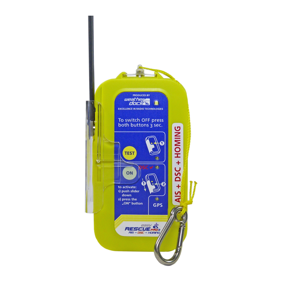
Functions Device overview Page 15 of 52... -
Page 16: Led Elements
LED Elements 4.2.1 LED „FLASH“ The white LED flashes when the Rescue Transmitter being activated (ON or TEST mode). This powerful LED assists in finding the person in distress in darkness or bad weather conditions. 4.2.2 LED „TEST“ The yellow LED "TEST" blinks when the Rescue Transmitter is in TEST mode. -
Page 17: Led „Gps
(Only applies to devices of the easyRESCUE-PRO/-PRO series) In those devices with DSC function, the green DSC LED is usually off during operation and only blinks when the Rescue Transmitter receives a DSC confirmation. This may be possible in 2 cases:... -
Page 18: Sliding Cover
The TEST button can be accessed at any time. Standard (Only applies to devices of the easyRESCUE A040, A040-BW series) By pulling down the slide, the "TEST" button can be released, by pressing the slide strongly upwards, the "ON"... -
Page 19: On Mode (Alert)
After activation, the upper Flash LED starts blinking at an interval and the Rescue Transmitter starts sending AIS emergency signals. (See chapter 3.1) 4.4.1.2 DSC Alert (Only applies to devices of the easyRESCUE-PRO/-PRO series) DSC alarming is initiated simultaneously. (See chapter 3.2) 4.4.1.3 Homing Signal (121.5 MHz) -
Page 20: Overview Triggering Functions
4.4.2 Overview Triggering Functions A040- A040- A04003- A040 A049 BW-COM Manual ✓ ✓ ✓ ✓ ✓ activation Water ✓ ✓ ✓ ✓ activation Magnet ✓ ✓ ✓ activation 4.4.2.1 Manual Activation By pushing the slider down, the button "ON" is exposed and can be activated. -
Page 21: Activation Via Water Contact
4.4.2.2 Activation via Water Contact (Does not apply for asyRESCUE-A040, easyRESCUE-A040- ATEX, easyRESCUE-A049, easyRESCUE-A049-ATEX) If the device is submerged for more than one second, it activates automatically. In this case, a water contact between the antenna axis and the back panel screw is recognized. The spatial separation of the two measuring contacts ensures that the device is not triggered by gushing water. -
Page 22: Deactivation
4.4.3 Deactivation By pressing the two buttons simultaneously for more than 3 seconds, the ON Mode and therefore the Rescue Transmitter can be switched off. For quitting TEST mode, press button TEST for more than 3 seconds. Otherwise the Rescue Transmitter continues to operate until the battery is flat. - Page 23 Please proceed as follows to perform a function test: 1) Make sure to have a clear view to the sky in order to have a flawless GPS reception. 2) Press the "TEST" button. 3) All four LEDs will light up for 1 second to indicate that the TEST mode has started.
- Page 24 7) After completion of the test, the device switches off automatically. easyRESCUE-PRO, easyRESCUE-PRO In addition to the AIS telegrams, two DSC telegrams are sent to the programmed MMSI numbers. One of them, immediately after turning it on without any position information, another one after obtaining the GPS fix with position information.
-
Page 25: Installation Details
Installation Details Life Vest (Only applies to devices of A040-BW-COM an, A040-PRO and A04003 series) For the installation of an easyRESCUE Rescue Transmitter, your life vest needs to have a special pocket. vests company Secumar need A040-BW-COM/A040-PRO/A04003 device;... -
Page 26: Accessories
Accessories 5.2.1 Belt clip (Accessories: only for the devices A040 and A049) With the belt clip you can easily attach the Rescue Transmitter to a belt on your body or to a buoyancy foam jacket, for example. A cord which is rolled up in a holder is connected to the device so that the Rescue Transmitter cannot go adrift when it is removed from the bracket. -
Page 27: Telescopic Rod
5.2.2 Telescopic Rod (Available as separate accessory) With the telescopic rod you can bring the Rescue Transmitter to more than 1 meter above sea level if the life boat does not have higher superstructures for mounting the bracket. The bracket incl. Rescue Transmitter and telescopic rod are buoyant. -
Page 28: Attachment To Life Raft
5.2.3 Attachment to Life Raft By means of the telescopic rod, belt clip or neoprene bag, the device can be fixed in an elevated position to a life raft or life boat. (Antenna nadir > 1 m above the water is recommended) Page 28 of 52... -
Page 29: Neoprene Bag
5.2.4 Neoprene bag (Available as separate accessory) The neoprene bag (suitable for attaching it to the arm, a life raft or mast) is available under item number B066. Page 29 of 52... -
Page 30: Programming Of The Mmsi For Dsc Alerts
Programming of the MMSI for DSC Alerts (Only applies to devices of the easyRESCUE-PRO/-PRO series) Within the 5 years, as specified by SOLAS, until the next replacement of batteries becomes necessary, a total of 30 minutes is scheduled for the programming. This does not impair the operation of 96 hours (AIS operation) or 24 hours (AIS &... -
Page 31: Programming Via App
2) via direct DSC "individual call" from the DSC radio device of the mother ship, 3) with the programming station (easyPROGRAMMER, A124) on a PC via USB connection. Programming via App (Only applies to devices of the easyRESCUE-PRO(BT & BT-LV), easyRESCUE-PRO series) ® This can be done via BLUETOOTH... - Page 32 Rescue Transmitter switches off after 3 minutes. 5) Open the app. 6) Tap “Search easyRESCUE- PRO” to connect the app with the Rescue Transmitter. 7) With a short glance on the rear side of the Rescue...
- Page 33 9) A window will pop up. 10) Tap any of the 8 fields to enter an MMSI number. 11) Now type the desired MMSI. 12) Then tap "Program". Page 33 of 52...
- Page 34 13) The entered MMSI is now stored in the internal memory of the Rescue Transmitter. In this example "Ship ID #1" 14) The Rescue Transmitter confirms the correct input and storage of the MMSI with a beep tone. 15) This process can be repeated until all 8 memory spaces are filled in.
- Page 35 17) Tap the small arrow pointing to the left to exit the programming window. 18) By tapping on "Turn Off" the Rescue Transmitter is switched off. This is also accompanied by a beep. 19) If the Rescue Transmitter is not switched off manually, it switches off automatically after 3 minutes without any activity.
-
Page 36: Programming Via Dsc „Individual Call
Programming via DSC „Individual Call“ 1) Go to the “Individual Call” settings of your VHF radio and key in the Rescue Transmitter’s Unit-ID (MMSI). 2) Press the “TEST” button of the Rescue Transmitter for more than 3 seconds until a triple beep is heard. Thereby all 4 LEDs light up. -
Page 37: Programming Via Programming Station
The stored MMSI numbers cannot be changed or deleted by means of the radio device. When attempting to program a 9 number into the Rescue Transmitter, there will be a warning with a quick successive beep tone and the yellow "TEST" LED blinks quickly. For safety reasons you must confirm this warning by pressing the "TEST"... -
Page 38: Technical Specification
Technical specification AIS SART Description Value Case Measurements (L) 130mm * (W) 70mm * (H) 30mm 250 - 350 grams Total Weight (depending on variant) Industrial pack Battery 4 Lithium Cells (CR17345) à 3V AIS 1: 161.975 MHz Frequencies AIS 2: 162.025 MHz Transmission Power 2 Watt (radiated) 50 Channel Receiver with integrated... - Page 39 Msg.1: AIS position report (dynamic data) are sent • 6 -8 times per minute • Unit ID: 9-digit identification number (unique in the world) • Speed over Ground (SOG) • Course over Ground (COG) Supported AIS • GPS position Notifications in _______________________________ Transmitting Operation Msg.14:...
-
Page 40: Dsc Mob (Supplemental To 7.1)
DSC MOB (supplemental to 7.1) (Only for devices of the easyRESCUE-PRO/-PRO series) Description Value "Closed loop" and "open loop" DSC operation pursuant to RTCM 11901.1 Frequencies DSC Frequency: 156.525 MHz Transmission Power 0.5 Watt Operation Time In common operation of AIS & DSC: up... -
Page 41: Troubleshooting
Troubleshooting Problem Cause Solution “TEST” LED is No GPS reception The easyRESCUE needs a blinking but GPS signal to perform the the “GPS” LED test, which may be has not started difficult to receive in blinking even some circumstances. after 5 minutes. - Page 42 Problem Cause Solution The Rescue Older plotters or those Old firmware of Transmitter is with old firmware may in the plotter not displayed some cases interpret the on the plotter SART messages incorrectly. Please contact the manufacturer of your plotter. The Rescue The Rescue Transmitter is Overdriving of...
-
Page 43: Maintenance
Maintenance The following maintenance and / or inspection is required for the Rescue Transmitters of the easyRESCUE series. The device should be activated in test mode by pressing the "TEST" button after 6 months, however under no circumstances later than after 12 months. -
Page 44: Contact And Product Support
Contact and Product Support Even though Weatherdock AG always strives to edit all publications with the highest level of accuracy, this manual may contain errors or ambiguities. In addition, the incumbent changes to the manuals are at the sole discretion of the company Weatherdock and may be made without giving prior notice. -
Page 45: Easyrescue - Database
– Database In order to make the Rescue Transmitter even more safe and more effective, we provide a database on our website where personal and relevant data can be stored. By providing this information you enable the official first responders, such as DGzRS, to act effectively and quickly in case of an emergency. -
Page 46: License Agreement
License Agreement By using the easyRESCUE you agree to the terms of the following warranty provisions. Please read these provisions thoroughly. Weatherdock AG grants a limited license for the use of the device under normal operation conditions of the product. - Page 47 The Weatherdock AG easyRESCUE does not contain parts which require repair by the user. Please contact your easyRESCUE distributor if you have a problem with the device. Any attempt to open, change and modify the device will void the warranty claims and may cause irreparable damage to the device.
- Page 48 / or coastal radio stations within AIS reach and inform them about your distress situation and position. The easyRESCUE-PRO can send an official distress call to a distant rescue service (e.g. DGzRS) via its DSC function. This is not a minor offense! All trademarks used in this document are the property of the respective companies.
-
Page 49: Notes
Notes Page 49 of 52... - Page 50 INDEX 121.5 MHz ......19 Database ......45 121.5 MHz......14 Deactivation ....22 Device overview ..... 15 DSC Alert ......19 Abbreviations ....6 DSC Function ....12 Abstract ......10 Accessories .....26 Activation ....20, 21 Homing Function ... 14 AIS Emergency Signal ..19 Homing Signal ....
- Page 51 Maintenance ....43 Manual Activation ..20 Safety information ... 7 Sliding Cover ....18 Neoprene bag ....29 Technical specification ... 38 Test mode ...... 22 ON mode ......19 Troubleshooting ..... 41 Programming of the MMSI Warranty ......46 ....30, 31, 36, 37 Water contact ....
- Page 52 Weatherdock AG Emmericher Strasse 17 D - 90411 Nürnberg Tel.: +49 (0) 911 – 37663830 Fax: +49 (0) 911 - 37663840 www.easyais.com info@weatherdock.de Page 52 of 52...
Need help?
Do you have a question about the A040-BW-COM and is the answer not in the manual?
Questions and answers