Table of Contents
Advertisement
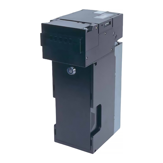
Bill Acceptor
EBA-30/31-SD3(EBA-30/31)
EBA-32/33-SD3(EBA-32/33)
EBA-34/35-SD3(EBA-34/35)
CHAPTER 1
Contents
Product Name & Specifications
1. Product Name
2. Precautions
3. Features
4. Component Names
5. General Specifications
6. Retrieving Bills
7. Cabling
8. Outside Dimensions
9. Country Codes
Copyright © 1998 Japan Cash Machine Co.Ltd. All rights reserved.
Issue
01/2006
Advertisement
Chapters
Table of Contents

Related Manuals for JCM EBA-34

Summarization of Contents
Chapter 1: Product Name & Product Specifications
1. Product Name (Model Name + Type)
Details the naming convention for EBA products, including model and type codes.
2. Precautions
Provides essential safety and handling guidelines for operating the bill acceptor.
3. Features
Highlights the key operational features of the EBA-3X-SD3 bill acceptor.
4. Component Names
Identifies and labels the main components of the bill acceptor unit.
5. General Specifications
Outlines the technical specifications, performance, and operating parameters.
6. Retrieving Bills
Explains the procedure for safely accessing and removing bills from the unit.
7. Cabling
Details the necessary connectors and recommended wiring for system integration.
8. Outside Dimensions
Provides detailed drawings and measurements for physical installation.
9. Country Codes
Lists country codes used for banknote acceptance and software configuration.
Chapter 2: Operation and Maintenance
1. Installation
Details the procedure for physically mounting the bill acceptor unit.
2. Interface
Describes the various communication interfaces supported by the EBA series.
3. External Connection Circuit
Provides schematic diagrams for connecting the EBA unit to external systems.
4. Pin Assignment
Details the pin assignments for various interface connectors on the CPU board.
5. Connector
Identifies the acceptor's connectors and their mating components for system connection.
6. Description of DIP switches
Explains the function and settings of DIP switches for operational configuration.
7. Operational Flow
Illustrates the step-by-step process of bill acceptance and operation.
8. Clearing Bill Jam
Provides instructions for safely removing jammed bills from the unit.
9. Cleaning / Preventive Maintenance
Guides on cleaning procedures and routine maintenance for optimal performance.
Chapter 4: Disassembly Instructions
1. Disassembling Complete Unit
Step-by-step guide to completely disassemble the bill acceptor unit.
2. Disassembling Stacker Unit
Detailed instructions for taking apart the stacker unit into its components.
3. Disassembling Acceptor Head Unit
Procedure for disassembling the main acceptor head unit.
4. Disassembling F-Guide Unit
Instructions for disassembling the F-Guide unit.
5. Disassembling U-Guide Unit
Instructions for disassembling the U-Guide unit.
6. Disassembling D-Guide Unit
Instructions for disassembling the D-Guide unit.
Chapter 5: Wiring Diagrams
1. EBA-30/31 Wiring Diagram
Schematic diagram illustrating the wiring for EBA-30/31 models.
2. EBA-32/33 Wiring Diagram
Schematic diagram illustrating the wiring for EBA-32/33 models.
3. EBA-34/35 Wiring Diagram
Schematic diagram illustrating the wiring for EBA-34/35 models.
Chapter 6: Troubleshooting
1. Outline
Introduction to troubleshooting, identifying common issues and basic checks.
2. Bill Acceptance Test
Procedure for conducting a bill acceptance test to diagnose issues.
3. Error Classification (Malfunction or Rejection)
Categorizes errors based on LED blinking patterns and failure types.
4. Trouble Shooting
Provides detailed troubleshooting steps for various operational problems.
Chapter 7: Calibration, Software Download, and Diagnostics
1. VM-30 Descriptions
Overview of the VM-30 Test Bench, its parts, functions, and connectors.
2. Calibration
Procedure for calibrating optical and magnetic sensors for optimal performance.
3. Downloading Software to Flash Memory
Guide for upgrading or installing software onto the CPU board's flash memory.
4. Writing Serial Number (for ID-0E3 only)
Instructions for writing the unit's serial number to EEPROM for specific models.
5. Diagnostics
Details test modes, DIP switch settings, and sensor tests for diagnosing issues.
Need help?
Do you have a question about the EBA-34 and is the answer not in the manual?
Questions and answers