Advertisement
Advertisement

Related Manuals for Geo BJ 120


Summary of Contents for Geo BJ 120
- Page 1 OPERATION AND MAINTENANCE MANUAL...
-
Page 2: Table Of Contents
CONTENTS INTRODUCTION ..............................3 GENERAL INFORMATION ..........................4 SAFETY NOTES..............................7 SPECIFICATIONS............................12 ....................................14 ASSEMBLY ................................. 15 OPERATOR REQUIREMENTS ........................34 MAINTENANCE ..............................36 PARTS DRAWINGS AND LISTS ........................25... -
Page 3: Introduction
INTRODUCTION GEO wants to thank you for having chosen one of its products. The technological evolution and the new request of the agricultural world have pushed our firm to a continue improvement, focused on the product, on the quality of the materials and on the quality of work. -
Page 4: General Information
GENERAL INFORMATION Information about the manual The using prescriptions shown in this handbook must be carefully observed to obtain the best performances, to assure the greatest duration of the different parts and to avoid damages to the machine and accidents to the operator. lt is advised the careful reading of the present handbook, to deepen the knowledge of the MOWER BAR, before starting to use The present manual is to be considered an integral part of the machine, it must go with the machine in case of resale and till its demolition. - Page 5 2 IDENTIFICATION OF THE MACHINE You will find on frame of each machine: the EC mark and a plate reporting the information about the constructor, the model and the serial number, the year of construction, the weight. EC Identification plate...
-
Page 7: Safety Notes
Operator Safety Instructions and Practices WARNING: Engine exhaust and certain vehicle components contain or emit chemicals. WARNING: Battery posts, terminals and related accessories contain lead and lead compounds, chemicals known to cause cancer, birth defects or other reproductive harm. ( SG-31) WARNING: The rotating parts of this machine continue to rotate even after it has been turned off. - Page 8 DANGER NEVER use drugs or alcohol immediately before or while operating the Tractor and Implement. Drugs and alcohol will affect an operator’s alertness and coordination and therefore affect the operator’s ability to operate the equipment safely. Before operating the Tractor or Implement, an operator on prescription or over-the-counter medication must consult a medical professional regarding any side effects of the medication that would hinder their ability to operate the Equipment safely.
- Page 9 DANGER Do not operate the implement while wearing loose fitting clothing. Entanglement of the clothing with the rotating elements can result in serious injury or even death. Stay clear of all rotating elements at all times. Equipment Operation Safety Instructions and Practices WARNING Never leave the Tractor and Implement unattended while the Implement is in the lifted position.
- Page 10 WARNING Operate the Tractor and/or Implement controls only while properly seated in the Tractor seat with the seat belt securely fastened around you. Inadvertent movement of the Tractor or Implement may cause serious injury or death. WARNING In case of mechanical difficulty during operation, place the transmission in the park position, set the parking brake, shut down all power, including the engine and remove the key.
- Page 11 -Do Not operate the Mower on a Tractor with an underframe exhaust. -Do Not smoke or have an open flame near the Mower and Tractor. -Do Not drive into burning debris or freshly burnt areas. -Ensure slip clutches are properly adjusted to prevent excessive slippage and plate heating. - Never allow clippings or debris to collect near drivelines, slip clutches, and gearboxes.
- Page 12 Point lift lever is fully raised and in the latched transport position. Dropping implement in transport can cause serious damage to the tractor and/or Implement and possibly cause the operator or others to be injured or killed. WARNING Allow sufficient clearance for the Implement to swing outward while turning. Implements carried behind the Tractor will swing outside the tire path when making turns.
-
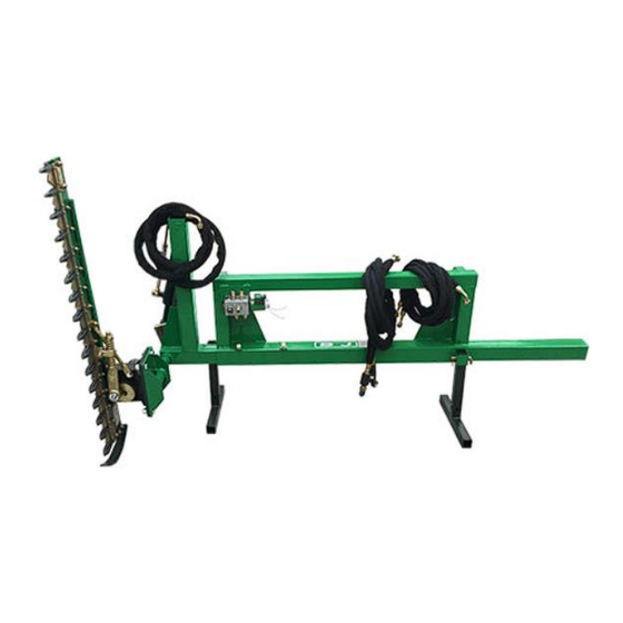
Page 14: Specifications
SPECIFICATIONS Connection: Euro-hitch • Drive mower bar: hydraulic • Cutting width: 1.200 – 1.500 – 1.800 mm • Brush cutting diameter (max.): 2-4 cm • Sideshift: 800 mm • Working speed: 2 - 4 km/h • Hydraulic connections: 1x double acting •... -
Page 15: Assembly
ASSEMBLY You will further need lugs to make the General information: connection and a cable extension for the specific 12V socket on your machine. A Read and ensure you understand the full changeover switch (e.g. pressure or toggle assembly instructions before you begin switch) is also required to be able to operate assembling your machine. - Page 16 terminals connected cable clamps. (Push/Position A = cylinder control, Release/Position B = hydraulic motor) Fig. A control valve with power cables Fig. B Cable lugs connected...
- Page 17 1. Remove transport packaging Remove the transport packaging When opening the steel crate, beware of sharp edges on the locking mechanisms. 2. Scope of delivery Remove all of the wood packaging and protective film. Remove all loose parts and put them aside for later use.
- Page 18 Connection your machine with the European attachment and secure with the locking mechanism (Fig. 8 to 10). Fig. 8 Attach Fig. 9 Secure and lock Fig. 10 Secured attachment 4. Assembling the sickle bar frame normally be needed 3 to 4 times. After tightening screw 6, screw 1 will have Attach the sickle bar frame and the lever arm as loosened again.
- Page 19 Be sure the to secure the cutter bar against dropping during installation. Note the specified angles to allow the cutter bar to rotate properly during operation. Fig. 14 Attached frame Fig. 11 Flange with axle Fig. 13 Correct position Fig. 12 Accessories and taper socket Fig.
- Page 20 During the following steps 5 and 8, be Groove sure the sickle bar is installed in the upright position as shown in figure 18 (“protruding slightly"). The angle can be adjusted via the lever arm using the taper socket. If it doesn’t fit straight away it may need to be readjusted with the taper socket.
- Page 21 5 . Installing the hydraulic cylinder Fig. 21 Correct order Install the hydraulic cylinder as shown in figures 19-23. Please note, the mount for the extending cylinder rod itself must be installed to the bottom of the lever arm. Align the rods for the flow regulator and the check valve.
- Page 22 Connect the valve as shown in figures 24 to 29. Fig. 26 Screws and nuts Fig. 27 Flange on the European attachment Fig. 24 Electromagnetic control valve Fig. 28 Correct order...
- Page 23 Fig. 29 Correct order Fig. 32 Blade drive brace 7. Checking the screws on the sickle bar Always check all screw connections are tight and seated correctly before every use. This particularly applies to the screws for the blade drive shown in figures 30 to 36. Fig.
- Page 24 Fig. 39 Positioning the flange Fig. 36 Spring with lock nut 8. Connecting the sickle bar to the main frame Attach the sickle bar as shown in figures 37 to 42. Be careful not to hurt yourself on the sharp blades and be sure to have a second person help you with this step.
- Page 25 Fig. 38 Screws and nuts Fig. 42 Correct installed position...
- Page 27 9 . Connecting the hydraulic hoses The electric solenoid valve comes with the hydraulic connections and flow regulator installed. (figure C) Fig. 44 Hoses to the cylinder Fig. C Pre-assembled changeover valve Be sure to connect the included hydraulic lines correctly as shown in figures 43 to 61. Be sure not to crush the hydraulic lines, including when operating the machine.
- Page 28 Fig. 48 Machine connection (example) Fig. 52 First connection to the hydraulic Fig. 46 First connection to the machine Fig. 43 Hoses to the hydraulic motor Fig. 47 Flow regulator with protective cap motor...
- Page 29 Fig. 49 Second connection to the machine Fig. 53 First connection on the hydraulic motor Fig. 50 Flow regulator with protective cap Fig. 54 Connection to hydraulic motor two Fig. 51 Machine connection (example)
- Page 30 Fig. 55 Second hydraulic motor connection Fig. 59 Second connection on the cylinder Now check all hydraulic connections are seated correctly and tight. This applies to all hose connections, flow regulator, check valve and connections on the actual machine. Once adjusted the flow control valve must be secured with the lock screw.
- Page 31 10. Adjusting the displacement The machine has a mechanical sickle bar displacement. It can be adjusted laterally to Fig. Minimum extension the mowing conditions in a horizontal direction. To do so, slightly loosen the screws and lock nuts, move the extension to the desired position (if necessary with a 2 person) and secure the extension with screws and lock nuts again.
- Page 32 11. Lubricating the machine The machine needs to be lubricated prior to first use and regularly thereafter. You will need a grease gun and suitable multipurpose grease (not graphite grease). Figures 66 to 70 show the location of lubricating points. You will need spray or similar to lubricate the sickle bar.
- Page 33 Fig. 68 Bottom cylinder Fig. 69 Top cylinder Fig. 66 Blade drive Fig. 70 Lubricate the blade bar with spray 12. Storage legs If the machine will not be used for a longer period, secure the legs and store the machine on it. Always secure with the bolts.
-
Page 34: Operator Requirements
Fig. 73 Left leg Fig. 72 Order Fig. 74 Right leg 13. Flow regulator Set all flow regulators to minimal flow before first use and open as necessary. Fig. 75 Flow regulator (example) OPERATOR REQUIREMENTS Safe operation of the unit is the responsibility of a qualified operator. A qualified operator has read and understands the implement and tractor Operator’s Manuals and is experienced in implement and tractor operation and all associated safety practices. - Page 35 safety signs are affixed to the implement and tractor. If any part of the operation and safe use of this equipment is not completely understood, consult an authorized dealer for a complete explanation. If the operator cannot read the manuals for themselves or does not completely understand the operation of the equipment, it is not the responsibility of we to read and explain the manuals, safety practices, and operating instructions to the operator, but operator itself.
-
Page 36: Maintenance
MAINTENANCE LUBRICATION Grease Points All grease points shown in FIGURE 5-1 below should be greased before operating the machine. To make greasing easier by relieving the weight form the pivot pins, rest the rotor unit on the ground, stop tractor engine and operate control levers in both directions. - Page 37 This manual cannot possibly cover all of the potentially hazardous situations you will encounter. By being familiar, though, with the safety rules, operating and maintenance instructions in this manual you can help prevent accidents. The objective of this manual is to help make you a better operator.
-
Page 38: Parts Drawings And Lists
PARTS DRAWINGS AND LISTS... - Page 39 PART NO. Name & Specifications CH150.001 Hedge trimmer CHJ150.011 Hanging Weldment(EURO Hitch) CHG150.011 Hanging Weldment(SMS Hitch) CHS150.011 Hanging Weldment(Skidder Hitch) CHJ150.012 Beam Weldment CHJ150.013 Rotation Seat Weldment GB/T889.1‐2000 Lock Nut M20 GB/T97.1‐1987 Plain Washer Key A 8x22 GB/T1096‐1979 CHJ150.102 Bearing 30*34*30 GB/T5783‐2000 Bolt M14*35 GB/T889.1‐2000...
Need help?
Do you have a question about the BJ 120 and is the answer not in the manual?
Questions and answers