Table of Contents
Advertisement
Advertisement
Table of Contents

Related Manuals for WABCO CAN Repeater

Summarization of Contents
Safety Information and Precautions
Risk of Injury
General safety precautions to prevent personal injury during vehicle operations.
Fire Hazard
Safety measures to mitigate fire risks in the workspace and during operation.
Avoiding Electro-static Discharge (ESD)
Procedures to prevent damage from electrostatic discharge during vehicle build and repair.
System Overview and Functionality
CAN Router Functionality
Explanation of the CAN Router's role in managing CAN signals for Trailer EBS systems.
CAN Repeater Functionality
Role of the CAN Repeater in amplifying CAN signals for extended trailer connections.
System Prerequisites and Configuration
Essential requirements and setup steps for CAN router/repeater with T-EBS.
System Certificates
Information regarding TÜV and informal certificates for CAN router/repeater compliance.
CAN Router and Repeater Components
CAN Router Component Description
Detailed description of the CAN Router unit and its electrical connections.
CAN Router Variants
Overview of different WABCO part numbers and housing symbols for CAN routers.
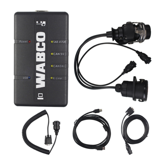
CAN Repeater Component Description
Detailed description of the CAN Repeater unit and its electrical connections.
CAN Repeater Variants
Overview of different WABCO part numbers and housing symbols for CAN repeaters.
Pin Assignments
Detailed pinout configurations for all CAN router/repeater connections.
Pressure Sensor 441 044 101 0 / 102 0
Technical details and application of the specified pressure sensor.
Cables Overview
Summary of cables used, their types, and corresponding trailer EBS applications.
Power Supply Cable Details
Specifications for power supply cables, including part numbers and connector types.
Sensor Cable Details
Specifications for sensor cables, including part numbers and connector types.
Installation and Maintenance Procedures
Mounting and Installation Overview
General guidance and initial steps for device mounting and system installation.
Installation Concept and Planning
Steps for selecting diagrams, identifying devices, and choosing appropriate cables.
Mounting the CAN Router / Repeater Unit
Specific instructions for physically installing the CAN router or repeater.
Mounting the Cables
Guidelines for securely and correctly routing and connecting cables.
Functional Testing Procedure
Steps for verifying the system's operation after installation.
Fuses and Protection
Information on internal fuses, their purpose, and indication of faults.
Replacing a Fuse
Step-by-step instructions for safely replacing a blown fuse in the unit.
Diagnostic Procedures and Software
Diagnostic Port Information
Details on the diagnostic port and its connection requirements.
ISO7638 Interface Connection
How to connect diagnostic equipment using the ISO7638 towing vehicle/trailer interface.
Required Hardware for Diagnostics
Specifications for necessary hardware like PCs and diagnostic interfaces.
Diagnostic Software Overview
Methods for acquiring and installing the diagnostic software.
Using Trailer CAN Router-Repeater Software
Key diagnostic tasks including fault memory and status monitoring.
Monitoring External Pressure Sensor
Managing fault monitoring for the external pressure sensor.
ECU Software Update Procedure
Instructions for updating the electronic control unit software.
Technical Appendix and Diagrams
Diagnostic Messages List
A comprehensive list of error codes, component references, and fault types.
Diagnostic Message Notes and Troubleshooting
Detailed explanations for specific diagnostic messages and troubleshooting advice.
Drilling Template for Mounting
A printed template to guide drilling for device mounting.
Diagram: CAN Router 841 601 287 0
Wiring diagram for CAN Router 841 601 287 0 in specific trailer setups.
Diagram: CAN Router 841 701 228 0
Wiring diagram for CAN Router 841 701 228 0 in specific trailer setups.
Diagram: CAN Router 841 601 245 0
Wiring diagram for CAN Router 841 601 245 0 in specific trailer setups.
Diagram: CAN Repeater 841 701 055 0
Wiring diagram for CAN Repeater 841 701 055 0 in specific trailer setups.
Diagram: CAN Repeater 841 701 057 0
Wiring diagram for CAN Repeater 841 701 057 0 in specific trailer setups.
Diagram: CAN Repeater 841 701 058 0
Wiring diagram for CAN Repeater 841 701 058 0 in specific trailer setups.
Need help?
Do you have a question about the CAN Repeater and is the answer not in the manual?
Questions and answers