Table of Contents
Advertisement
Quick Links
- 1 Table of Contents
- 2 About Thi S Manual .Nnnnnnnnnnnnnnnnnnnnnnnnnnnnnnnnnnnnnnnnnnnnnnnnnnnnnnnnnnnnnnnnnnnnnnnnnnnnnnnnnnnnnnnnnnnnnnnnnnnnnnnnnnnnnnnnnnnnnnnnnnnnnnnnnnn
- 3 Display Setting .Nnnnnnnnnnnnnnnnnnnnnnnnnnnnnnnnnnnnnnnnnnnnnnnnnnnnnnnnnnnnnnnnnnnnnnnnnnnnnnnnnnnnnnnnnnnnnnnnnnnnnnnnnnnnnnnnnnnnnnnnnnnnnnnnnnnnnnnnnnnnnn
- 4 Fault Reference Code .Nnnnnnnnnnnnnnnnnnnnnnnnnnnnnnnnnnnnnnnnnnnnnnnnnnnnnnnnnnnnnnnnnnnnnnnnnnnnnnnnnnnnnnnnnnnnnnnnnnnnnnnnnnnnnnnnnnnnnnnnnnnnnnnnnn
- 5 Trouble Shooti Ng .Nnnnnnnnnnnnnnnnnnnnnnnnnnnnnnnnnnnnnnnnnnnnnnnnnnnnnnnnnnnnnnnnnnnnnnnnnnnnnnnnnnnnnnnnnnnnnnnnnnnnnnnnnnnnnnnnnnnnnnnnnnnnnnnnnnn
- Download this manual
Advertisement
Table of Contents

Related Manuals for Inverex Axpert King 5.2KW


Summarization of Contents
SAFETY INSTRUCTIONS
General Safety Precautions
Essential safety guidelines for unit operation, battery handling, and electrical connections, including warnings and cautions.
INTRODUCTION
Features
Lists key features of the MPPT solar inverter, such as pure sine wave output and built-in charge controller.
Basic System Architecture
Illustrates a typical system setup including PV modules, generator/utility, and battery for a complete running system.
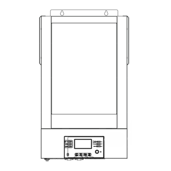
Product Overview
Inverter Component Identification
Identifies and labels the various input/output ports, indicators, and controls on the inverter unit.
INSTALLATION
Unpacking and Inspection
Details the items expected in the package and the initial inspection process before installation.
Preparation
Instructions for preparing the unit for mounting by removing the bottom cover and accessing internal components.
Mounting the Unit
Guidelines for selecting an installation location, ensuring proper clearance, and mounting the inverter securely.
INSTALLATION
Battery Connection
Explains how to connect the battery to the inverter, including cable specifications, terminal size, and torque values.
INSTALLATION
AC Input/Output Connection
Guides on connecting AC power input and output, including breaker recommendations and correct wiring polarity.
INSTALLATION
PV Connection
Details how to connect PV modules, including circuit breaker recommendations, cable size, and torque values.
INSTALLATION
PV Module Selection
Advises on parameters to consider when selecting PV modules for optimal performance and compatibility.
Final Assembly
Instructions to reattach the bottom cover after all wiring connections have been completed.
Communication Connection
Explains how to connect the inverter to a PC using a communication cable for monitoring software.
Dry Contact Signal
Dry Contact Signal Functionality
Explains the dry contact port's use for signaling external devices based on unit status and battery voltage levels.
OPERATION
Power ON/OFF
Instructions on how to turn the unit on and off using the power switch located on the case.
Operation and Display Panel
Describes the front panel layout, including LED indicators, function keys, and the LCD display.
OPERATION
LCD Display Icons
Explains the meaning of various icons displayed on the LCD screen for input, output, and configuration information.
OPERATION
Load Information
Details how load percentage, VA, and Watt values are displayed on the LCD screen.
Mode Operation Information
Explains icons indicating different operating modes like mains, PV, bypass, and charging status.
Mute Operation
Explains icons related to alarm status disabling and Bluetooth Low Energy (BLE) connectivity.
OPERATION
LCD Setting
Guides on how to enter setting mode and navigate through various configuration programs using the unit's buttons.
OPERATION
LCD Setting - Program 05-10
Details configuration options for programs such as battery type, auto restart, output frequency, and operation logic.
OPERATION
LCD Setting - Program 11-13
Details configuration options for programs related to utility charging current and SBU priority voltage points.
OPERATION
LCD Setting - Program 16-19
Details configuration options for programs such as charger source priority, alarm control, and auto return to display.
OPERATION
LCD Setting - Program 23-27
Details configuration options for programs like bypass function, fault code recording, and charging voltages.
OPERATION
LCD Setting - Program 29-37
Details configuration options for programs such as low DC cut-off voltage, charging time, and battery equalization settings.
OPERATION
LCD Setting - Program 39-40
Details configuration options for programs like equalization activation and time settings.
Display Setting
Display Setting - Input/Output Info
Explains how to cycle through and view input/output voltage, frequency, and PV information on the LCD.
Display Setting
Display Setting - Charging/Voltage Info
Explains how charging current, charging power, battery voltage, and output frequency are displayed on the LCD.
Display Setting
Display Setting - Load/Energy Info
Explains how load percentage, VA, Watt, and energy generation/consumption are displayed on the LCD.
Display Setting
Display Setting - Totals/Version Info
Explains how total energy generated/consumed and version information are displayed on the LCD.
Operating Mode Description
Standby and Fault Modes
Describes the unit's behavior and LCD indications in standby mode and various fault conditions.
Operating Mode Description
Bypass/ECO and Line Modes
Explains the operational characteristics and LCD indications for Bypass/ECO and Line modes.
Battery Mode
Details the operation and LCD indications when the unit is in Battery Mode, including power source and charging.
Fault Reference Code
Fault Code Descriptions
Lists fault codes, their corresponding events, explanations, and the relevant icon displayed on the unit for troubleshooting.
Warning Indicator
Warning Indicator Codes
Details warning codes, events, audible alarms, and flashing icons for user alerts and potential issues.
BATTERY EQUALIZATION
How to Apply Equalization Function
Steps to enable and apply battery equalization using LCD setting programs and methods.
When to Equalize
Describes the conditions under which the unit enters the Equalize stage, based on float stage and active commands.
BATTERY EQUALIZATION
Equalize charging time and timeout
Explains the charging process, constant-voltage regulation, and timeout handling during the Equalize stage.
SPECIFICATIONS
Table 1 Line Mode Specifications
Provides detailed electrical specifications for the inverter when operating in Line Mode, including voltage, frequency, and efficiency.
SPECIFICATIONS
Table 2 Battery Mode Specifications
Lists detailed electrical specifications for the inverter when operating in Battery Mode, including output, voltage, and power consumption.
SPECIFICATIONS
Table 3 Charge Mode Specifications
Details charging specifications for both Utility and Solar (MPPT) modes, including current, voltage, and algorithms.
SPECIFICATIONS
Table 4 ECO/Bypass Mode Specifications
Provides electrical specifications for the inverter when operating in ECO/Bypass modes, including input voltage characteristics.
SPECIFICATIONS
Table 5 General Specifications
Lists general specifications like SCC type, communication interfaces, safety certification, operating temperature, and dimensions.
TROUBLE SHOOTING
Startup and Basic Operation Issues
Addresses common problems like automatic shutdown, no response, unit working in battery mode, and indicator status.
Fault Code Troubleshooting
Provides solutions for specific fault codes such as overload, output short circuit, over-temperature, and battery issues.
Buzzer and Red LED Issues
Details troubleshooting steps for continuous buzzer beeps and continuous red LED indication, often related to fan or output faults.
Appendix I: Approximate Back-up Time Table
Back-up Time for 3.2KVA Model
Shows estimated backup times for the 3.2KVA model at various load levels and battery capacities.
Back-up Time for 5.2KVA Model
Shows estimated backup times for the 5.2KVA model at various load levels and battery capacities.
Need help?
Do you have a question about the Axpert King 5.2KW and is the answer not in the manual?
Questions and answers