
Related Manuals for King Air C90GTx

Summarization of Contents
CHAPTER 1 AIRCRAFT GENERAL
INTRODUCTION
Provides basic and background information needed to learn the details of airplane operation and performance.
GENERAL
Presents an overall view of the airplane, including external familiarization, cabin arrangements, and cockpit layout.
AIRPLANE SYSTEMS
Describes the airplane systems and components, focusing on pilot management for normal and emergency operations.
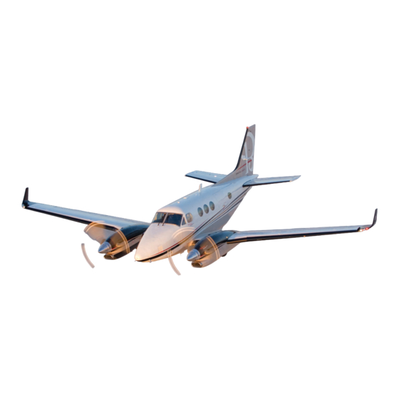
BEECHCRAFT KING AIR C90GTi AND C90GTx DESCRIPTION
Details the high-performance, conventional tail, pressurized, twin-engine turboprop airplane design and features.
Operating Speeds
Lists key operating speeds (VMO, VA, VLO, VFE) and stall speeds for C90GTi and C90GTx models.
CABIN ENTRY AND EXITS
Describes the cabin entry airstair door, its operation, and provisions for entry and exit.
FLIGHT DECK
Details the flight deck layout, instruments, controls, and seating arrangement for crew efficiency.
CONTROL SURFACES
Describes the conventional ailerons, elevators, and rudder, including their operation and control locks.
TIEDOWN AND SECURING
Provides procedures for securely mooring the airplane overnight or during high winds.
TAXIING
Explains ground turning radii and areas to be aware of due to propeller windstream.
SERVICING DATA
Outlines requirements for maintaining the aircraft and lists approved materials for servicing.
PRODUCT SUPPORT
Describes service facilities and parts availability for total support of the Super King Airs.
PREFLIGHT INSPECTION
Details the preflight inspection procedure divided into five areas for thorough aircraft examination.
Exterior Inspection
Lists the steps for the exterior inspection, covering cockpit, wings, landing gear, engines, and tail.
CHAPTER 2 ELECTRICAL POWER SYSTEMS
INTRODUCTION
Emphasizes the importance of understanding the electrical system for pilot workload and emergency situations.
GENERAL
Presents a description and discussion of the airplane electrical system and components.
BATTERY AND GENERATOR
Describes the 28-VDC system with its battery, starter/generators, and basic electrical symbols.
DC POWER DISTRIBUTION
Explains the "triple-fed" DC power distribution system and its three in-flight DC power sources.
BUS TIE SYSTEM
Details the system for protecting against high current flow using bus tie sensors and relays.
BUS ISOLATION
Explains how high-current sensing isolates affected buses by opening bus ties, ensuring system continuity.
LOAD SHEDDING
Describes the feature that automatically removes excess loads when power sources are reduced to battery only.
BATTERY
Details the lead-acid battery location and its connection to the hot battery bus for direct system power.
STARTER/GENERATORS
Describes the dual-purpose engine-driven units used as starters and generators.
DC GENERATION
Explains the generator phase of operation controlled by switches, GCUs, and their functions.
EXTERNAL POWER
Describes the external power receptacle and its connection to the electrical system when parked.
AVIONICS MASTER POWER
Details the avionics master switch and its schematic, used to control avionics power.
CIRCUIT BREAKERS
Explains the DC power distribution via two panels and procedures for tripped breakers.
CHAPTER 3 LIGHTING
INTRODUCTION
Covers the aircraft lighting system, including cockpit-controlled interior and exterior lights.
DESCRIPTION
Presents a description and discussion of the airplane lighting system and components.
Cockpit Lighting
Details the overhead light control panel with rheostat switches for all lighting systems in the cockpit.
CABIN LIGHTING
Describes the cabin lighting controls, including indirect fluorescent lights and NO SMOKING/FASTEN SEAT BELT signs.
EXTERIOR LIGHTING
Covers switches for landing lights, taxi lights, wing ice lights, and navigation lights on the pilot's subpanel.
CIRCUIT BREAKERS
Shows the lighting system circuit breakers located on the pilot's and copilot's panels.
CHAPTER 4 MASTER WARNING SYSTEM
INTRODUCTION
Explains warning and caution indicators as the first indication of trouble and necessary corrective actions.
GENERAL
Presents a description and discussion of the warning, caution, and advisory annunciator panel.
ANNUNCIATOR SYSTEM
Describes the annunciator panel, PRESS-TO-TEST switch, MASTER WARNING and CAUTION flashers.
MASTER WARNING FLASHER
Details the function of the red MASTER WARNING flasher and its interaction with red annunciators.
DIMMING
Explains the bright and dim modes of illumination for annunciators and flashers, and automatic selection.
TESTING AND LAMP REPLACEMENT
Covers testing annunciator lamps and the procedure for replacing faulty lamps.
ANNUNCIATOR PANEL DESCRIPTION
Lists warning, caution, and advisory annunciators and the cause for their illumination.
CHAPTER 5 FUEL SYSTEM
INTRODUCTION
Highlights the importance of fuel system understanding for competent and confident aircraft operation.
DESCRIPTION
Presents a description and discussion of the fuel system, including fuel cells, boost pumps, and drains.
FUEL SYSTEM
Describes the fuel system designed to simplify flight procedures and provide easy cockpit access.
FUEL TANK SYSTEM
Details the fuel tank system in each wing, including bladder-type tanks and the nacelle tank.
BOOST PUMPS
Explains the submerged boost pumps in nacelle tanks, their pressure supply, and associated annunciators.
FUEL TRANSFER PUMPS
Describes the system for maintaining nacelle tank fuel levels by transferring fuel from wing tanks.
FUEL CAPACITY
Provides information on the capacitance gaging system, total usable fuel capacity, and related indicators.
FUEL TANK VENTS
Details the fuel system venting through recessed ram scoop vents and heated external vents to prevent icing.
FUEL SYSTEM OPERATION
Explains the automatic fuel flow from wing tanks to center section tank and engine fuel pump operation.
FIREWALL SHUTOFF VALVES
Describes the firewall shutoff valves, their actuation by guarded switches, and power sources.
CROSSFEED OPERATION
Details crossfeeding fuel authorized for engine failure or electric boost pump failure.
FUEL DRAINS
Explains the importance of draining fuel sumps on tanks, pumps, and filters to check for contamination.
FUEL HANDLING PRACTICES
Provides procedures for fuel handling, including takeoff restrictions and contamination prevention.
FUEL GRADES AND ADDITIVES
Lists approved fuel grades, additives, and limitations for operation with aviation gasoline.
FILLING THE TANKS
Provides guidelines for filling aircraft fuel tanks, emphasizing nacelle tank servicing first.
DRAINING THE FUEL SYSTEM
Explains the procedure for draining fuel daily to remove water or contamination from low points.
CHAPTER 7 POWERPLANT
INTRODUCTION
Emphasizes the importance of powerplant knowledge for good power management, engine life, and safety.
GENERAL
Presents a description and discussion of the Pratt and Whitney PT6A turboprop engines and their operational practices.
ENGINES
Describes the PT6A series free-turbine turboprop engines and their basic terms.
TURBOPROP ENGINE RATINGS
Explains power measurement in Equivalent Shaft Horse Power (ESHP) and Shaft Horse Power (SHP).
ENGINE TERMS
Defines basic terms like N1, N2, NF, P3, and ITT necessary for understanding PT6A engine operation.
FREE-TURBINE REVERSE-FLOW PRINCIPLE
Explains the basic design of free-turbine, reverse-flow engines and their airflow path.
ENGINE AIRFLOW
Details the airflow path through the engine, from inlet to compressor, combustion chamber, and turbines.
ENGINE STATIONS
Explains engine station numbers used to identify points for pressure or temperature measurement.
ENGINE MODULAR CONCEPT
Describes the engine's division into gas generator and power sections for simplified installation.
COMPRESSOR BLEED VALVE
Explains the pneumatic valve that prevents compressor stalls by relieving excess airflow at low RPM.
IGNITERS
Details the engine start switches and the two spark-type igniters for positive ignition during engine start.
ACCESSORY SECTION
Describes the location of engine-driven accessories, except governors, mounted on the accessory gearbox.
LUBRICATION SYSTEM
Explains the dual function of the lubrication system: cooling/lubricating bearings and supplying oil to the propeller governor.
ENGINE FUEL SYSTEM
Describes the fuel control system, including boost pump, heat exchanger, fuel pump, and fuel control unit.
FUEL CONTROL UNIT
Explains the FCU's primary purpose of metering fuel to nozzles and its operation via condition levers.
FUEL PRESSURE INDICATORS
Details the FUEL PRESS annunciator illumination and its relation to boost pump pressure.
FUEL FLOW INDICATORS
Explains how fuel flow is sensed and indicated on the Engine Indicating System (EIS).
ANTI-ICING FUEL ADDITIVE
Discusses using engine oil to heat fuel and the necessity of anti-icing additive in icing conditions.
ENGINE POWER CONTROL
Explains how propeller levers and power levers control engine power via N1 governor and FCU.
ITT AND TORQUEMETERS
Covers temperature and torque limitations as primary operating parameters affected by ambient conditions.
ITT GAGE
Monitors interstage turbine temperature, a primary limiting indicator of engine power.
TORQUEMETER
Measures rotational force applied to the propeller shaft, indicating torque in ft-lb.
GAS GENERATOR TACHOMETER (N1)
Measures the rotational speed of the compressor shaft in percent of RPM.
CONTROL PEDESTAL
Describes the control pedestal with power levers, propeller levers, and condition levers.
Power Levers
Control engine power from idle to maximum, influencing N1 governor and fuel control unit.
Condition Levers
Selects idle speeds and influences N1 governor, controlling fuel flow and engine speed.
Propeller Levers
Set propeller RPM for takeoff, climb, and cruise, with manual and automatic feathering systems.
ENGINE LIMITATIONS
Details airplane and engine limits approved by the FAA and found in the POH Limitations section.
STARTER OPERATING TIME LIMITS
Specifies time limits for engine starters during the starting cycle to prevent damage.
Trend Monitoring
Recommends periodically recording engine parameters to establish performance characteristics.
PROPELLERS
Describes propellers and the associated system, including controls, operation, reversing, and feathering.
PROPELLER SYSTEM
Details propeller system operation and testing, focusing on constant-speed, full-feathering, reversing propellers.
Hartzell Four-Blade Propellers
Describes the advantages of Hartzell 90-inch, four-blade propellers, including lower tip speeds and less noise.
Blade Angle
Explains blade angle as the angle between the chord and the propeller's plane of rotation.
PRIMARY GOVERNOR
Describes the primary governor's function in converting variable-pitch propellers to constant-speed operation.
Primary Governor Operation
Explains how propeller levers adjust the primary governor for RPM and oil supply control.
LOW PITCH STOP
Details how the low pitch stop prevents propeller blades from reducing airflow over the empennage.
Low Pitch Stop Operation
Describes how the power lever controls the low pitch stop and Beta valve activation.
GROUND FINE AND REVERSE CONTROL
Explains the power lever linkage geometry for ground handling and reverse operation.
Ground Fine and Reverse Control Operation
Details how the Beta valve is repositioned by power levers to control propeller blade angle in ground fine/reverse.
OVERSPEED GOVERNOR
Provides protection against excessive propeller speed in case of primary governor malfunction.
Overspeed Governor Operation
Explains the hydraulic overspeed governor function and how to test it.
FUEL TOPPING GOVERNOR
Describes how the fuel topping governor limits propeller RPM by controlling fuel flow.
POWER LEVERS
Details the power levers' function in establishing gas generator RPM and controlling propeller blade angle.
Propeller Control Levers
Explains how propeller RPM is set using the primary governor and control levers.
AUTOFEATHER SYSTEM
Describes the automatic feathering system for immediate oil pressure dumping upon engine failure.
PROPELLER SYNCHROPHASER SYSTEM
Details the Type II synchrophaser system for matching propeller RPM and blade position.
Synchrophaser Operation
Explains how the synchrophaser automatically matches propeller RPM and blade phase relationship.
Propeller Synchroscope
Describes the synchroscope's function in indicating propeller RPM and synchronization.
CHAPTER 8 FIRE PROTECTION
INTRODUCTION
Covers the aircraft fire protection system, including engine fire detection and extinguishing.
GENERAL
Presents a description and discussion of the airplane fire protection system and components.
FIRE DETECTION SYSTEM
Describes the system designed to provide immediate warning in the event of fire in either engine compartment.
Fire Detection Test System
Details the rotary switch test for fire detector circuitry, checking for functional illumination.
FIRE EXTINGUISHING SYSTEM
Describes the optional engine fire extinguishing system with explosive cartridges and activation switches.
Fire Extinguisher Test System
Explains the test functions for the fire extinguisher system, checking bottle charge and squib firing circuitry.
CHAPTER 9 PNEUMATICS
INTRODUCTION
Explains the necessity of pneumatic and vacuum systems for various aircraft operations.
DESCRIPTION
Presents a description and discussion of pneumatic and vacuum systems, including sources and readings.
ENGINE BLEED AIR PNEUMATIC SYSTEM
Details the pneumatic system providing bleed air for surface deice, rudder boost, seals, and vacuum.
Pneumatic Air Source
Describes bleed air at maximum rate of 90 to 120 psi obtained from both engines.
VACUUM AIR SOURCE
Explains vacuum obtained from a vacuum ejector supplying the pressurization control system.
CABIN DOOR SEAL
Describes how the entrance door and escape hatch use pneumatic air to inflate seals after takeoff.
SURFACE DEICE SYSTEM
Covers protection of wing and stabilizer leading edges against ice accumulation using inflatable boots.
CHAPTER 10 ICE AND RAIN PROTECTION
INTRODUCTION
Emphasizes knowledge of icing conditions and anti-ice/deice systems for preventing ice formation.
GENERAL
Presents description and discussion of airplane ice and rain protection systems, including location and controls.
ICE PROTECTION SYSTEMS
Lists seven pilot-controlled anti-ice/deice systems, including surface, propeller, windshield, and engine anti-ice.
Surface Deice System
Details protection of wing and stabilizer leading edges using inflatable boots inflated by pneumatic pressure.
Propeller Deice System
Describes the electric deice system including heated boots, slip rings, brushes, timer, and ammeter.
Windshield Anti-Ice System
Explains the three-layer windshield structure with electrical heating elements and controls.
Windshield Wipers
Describes the separate windshield wipers for pilot and copilot, driven by a single electric motor.
ENGINE ANTI-ICE SYSTEM
Details the inertial vane system installed on each engine to prevent ice or foreign objects from entering.
ANTI-ICE CONTROLS
Explains how ice vane and bypass doors are controlled by switches in the ICE PROTECTION group.
ENGINE AIR INLET LIP HEAT
Describes heating of the air inlet lip by hot exhaust gases to prevent ice formation.
Pitot Mast Heat
Details the heated pitot masts on the aircraft nose that protect against ice accumulation.
Fuel Heat
Explains anti-ice systems to protect fuel flow through lines to the engine, preventing freezing.
Stall Warning Anti-ice
Covers the stall warning vane and plate heating to ensure against freeze-up during icing conditions.
Wing Ice Lights
Describes wing ice lights used to determine ice buildup on leading edges in icing conditions.
Precautions During Icing Conditions
Provides precautions for winter or icing conditions, including inspection and frost removal.
CHAPTER 11 AIR CONDITIONING
INTRODUCTION
States the importance of passenger comfort and safety, and operating environmental systems effectively.
DESCRIPTION
Presents description and discussion of air conditioning, bleed air heating, and fresh air systems.
ENVIRONMENTAL SYSTEM
Describes the system controlling pressure vessel environment, air circulation, and temperature.
UNPRESSURIZED VENTILATION
Explains fresh air ventilation from bleed air heating and ram-air scoop during unpressurized flight.
BLEED-AIR HEATING SYSTEM
Details how bleed air from engine compressors is used for cabin pressurization and heating.
ELECTRIC HEAT
Describes the electrical heater with eight heating elements for NORMAL and MAX HEAT operations.
COOLING SYSTEM
Explains cabin cooling provided by a refrigerant gas vapor-cycle refrigeration system.
ENVIRONMENTAL CONTROLS
Details environmental controls on the copilot's subpanel for automatic or manual system operation.
CHAPTER 12 PRESSURIZATION
INTRODUCTION
Explains the benefits of cabin pressurization for reducing oxygen need and handling system operations.
DESCRIPTION
Presents a description of the pressurization system, its components, and controls.
PRESSURIZATION SYSTEM
Details the system designed to provide a cabin environment with sufficient oxygen for normal breathing.
AIR DELIVERY SYSTEM
Explains how bleed air from engines is utilized for pressurization, mixing with ambient air.
CABIN PRESSURE CONTROL
Describes the adjustable cabin pressurization controller and its indicator dials for cabin altitude and differential.
PREFLIGHT CHECK
Details the functional check of the pressurization system during runup and prior to takeoff.
IN FLIGHT
Describes cabin pressure altitude changes during climb and system maintenance of selected altitude.
DESCENT
Explains setting cabin altitude and rate control for descent and preparation for landing.
FLOW CONTROL UNIT
Details the unit in each nacelle controlling bleed air for pressurization, heating, and ventilation.
CHAPTER 14 LANDING GEAR AND BRAKES
INTRODUCTION
Aids the pilot in proper handling of landing gear and brake operations, including inspection points.
GENERAL
Presents description and discussion of the landing gear system, controls, limits, and indicator system.
LANDING GEAR SYSTEM
Describes the landing gear system, including components and operation of assemblies.
LANDING GEAR ASSEMBLIES
Details the components of each landing gear assembly: shock strut, torque knee, drag leg, actuator, wheel, and tire.
Operation
Explains how the upper drag legs and shock struts attach to the aircraft structure and operate.
WHEEL WELL DOOR MECHANISMS
Describes the landing gear doors, their mechanical actuation by gear movement, and their operation.
STEERING
Details the direct linkage to rudder pedals for nosewheel steering when the nose gear is down.
HYDRAULIC LANDING GEAR
Explains the electrically controlled and hydraulically actuated tricycle landing gear system.
LANDING GEAR EXTENSION AND RETRACTION
Describes how nose and main gear assemblies are extended and retracted by hydraulic actuators.
HYDRAULIC FLUID LEVEL INDICATION SYSTEM
Details the caution annunciator 'HYD FLUID LOW' and its testing procedure.
Control
Explains how the hydraulic power pack motor is controlled by the landing gear switch handle.
Position Indicators
Describes the landing gear position indication assembly with three lights indicating gear status.
LANDING GEAR WARNING SYSTEM
Provides warnings to the pilot about landing gear position during specific flight regimes via horn and lights.
FLAP AIRSPEED LIMITS
Shows maximum speeds and operating range of flaps (VFE) and flap speeds for approach.
RUDDER BOOST SYSTEM
Describes the system designed to aid the pilot in maintaining directional control during engine failure.
KING AIR WHEEL BRAKES
Details the non-assisted hydraulic brake system with multi-disc dual hydraulic brakes.
SERIES BRAKE SYSTEM
Explains the dual brakes plumbed in series, with each rudder pedal attached to its own master cylinder.
PARKING BRAKE
Describes the parking brake system utilizing regular brakes and a set of valves.
BRAKE SERVICE
Covers brake system servicing, primarily maintaining hydraulic fluid level and checking connections.
BRAKE WEAR LIMITS
Explains automatic brake lining adjustment and periodic check for dimension 'A' not reaching zero.
COLD WEATHER OPERATION
Provides checks for brakes and tire-to-ground contact for freeze lock-up in cold weather.
CHAPTER 15 FLIGHT CONTROLS
INTRODUCTION
Emphasizes flap system operation and limits for optimum performance and describes rudder boost system.
DESCRIPTION
Presents description and discussion of the flap system and the rudder boost system.
FLAPS SYSTEM
Details the four-segment Fowler-type flap system, its controls, limits, and operation.
Flap Operation
Describes flap selection to three positions (up, approach, down) and go-around initiation.
LANDING GEAR WARNING SYSTEM
Warns the pilot about landing gear position during specific flight regimes via horn and lights.
FLAP AIRSPEED LIMITS
Shows maximum speeds and operating range of flaps (VFE) for approach and beyond.
RUDDER BOOST SYSTEM
Explains the system designed to reduce pilot effort in single-engine flight configurations.
CHAPTER 16 AVIONICS
INTRODUCTION
Introduces the Collins Pro Line 21 avionics system as an integrated, reliable system for operation.
FLIGHT INSTRUMENTS
Covers the Electronic Flight Instrument System (EFIS) consisting of computers and data collectors.
ELECTRONIC FLIGHT INSTRUMENT SYSTEM (EFIS)
Describes EFIS components and how they provide flight, navigation, and engine data on LCD displays (AFD).
ADAPTIVE FLIGHT DISPLAYS (AFD)
Details the LCD Adaptive Flight Displays containing flight and navigation information, replacing round dial instruments.
Primary Flight Display (PFD)
Explains the PFD's primary function to show airplane attitude and dynamic flight data.
Line Select Keys
Describes the four line select keys (LSK) used in conjunction with displayed information on the AFD.
Attitude Display
Details the attitude display on the PFD, including flight director commands and navigation information.
Airspeed Display
Explains the airspeed display as a moving tape design showing current airspeed and related data.
Altitude and Vertical Speed Displays
Describes how altitude and vertical speed are indicated on the PFD using tape and digital readouts.
Heading and Navigation Displays
Covers displays for heading, current navigation source, radar/terrain, and traffic information.
RADAR Button
Controls display of weather radar menus on the PFD.
GCS Button
Controls ground clutter suppression selection of the weather radar.
TILT Control
Controls the weather radar antenna tilt angle.
RANGE Knob
Controls the scanning range shown on the MFD map and radar pictorial.
INTEGRATED AVIONICS PROCESSOR SYSTEM (IAPS)
Provides system integration and operating logic for Pro Line 21 avionics.
AIR DATA COMPUTERS (ADC)
Details the digital ADCs that convert dynamic flight data into electronic signals for various airplane systems.
ATTITUDE AND HEADING REFERENCE SYSTEM (AHRS)
Provides pitch, bank, and magnetic heading data to the onside displays.
PITOT AND STATIC SYSTEM
Describes independent pitot and static systems providing pilot and copilot flight indications.
OUTSIDE AIR TEMPERATURE
Details the digital OAT gage located on the left sidewall, displaying IOAT in Celsius or Fahrenheit.
STALL WARNING SYSTEM
Explains the system using a transducer, lift computer, and warning horn to detect stalls.
FLIGHT GUIDANCE SYSTEM (FGS)
Describes the integrated flight director (FD) and autopilot (AP) system including yaw damping.
FLIGHT GUIDANCE COMPUTERS (FGC)
Details how each FGC is supplied with input from AHRS, navigation data, and produces control signals.
FLIGHT GUIDANCE PANEL (FGP)
Explains how the FGP controls both FGCs and provides AP/FD mode selections.
AP Button
Controls autopilot engagement, requiring specific conditions to be met.
YD/AP Disconnect Switch-Bar
Removes power from the autopilot and yaw damper, causing both to disengage.
FD Mode Buttons
Describes how FD mode buttons control flight director command bars and automatic mode selections.
FD Buttons
Control display of flight director command bars on the PFD and their automatic activation.
UP/DOWN Pitch Wheel
Sets the vertical speed or pitch angle reference for VS mode or pitch mode.
ROLL Mode
The basic lateral mode, automatically activated when no other lateral mode is selected.
HDG Button
Controls selection of heading mode, annunciating HDG on the PFD when active.
HDG Knob
Simultaneously controls the heading bugs shown on both PFDs and the MFD.
PUSH SYNC Button
Resets the heading bugs to the current heading.
1/2 BANK Button
Limits the maximum bank angle to 15 degrees.
APPR Button
Controls selection of the approach mode, determined by active navigation source.
FLC Button
Controls the Flight Level Change mode for climb or descent towards preselected altitude.
SPEED Knob
Selects the IAS or Mach reference value for the FLC mode.
IAS/MACH Button
Selects Mach mode or IAS mode for the FLC Speed Bug and FLC reference.
ALT Button
Holds the aircraft at the current barometric altitude or levels off at a selected altitude.
Altitude Preselect Mode
Allows pilot to select a target altitude for automatic level off.
CONTROL WHEEL SWITCHES
Details switches on control wheels affecting FGS operation.
DISC TRIM AP/YD Button
Disengages the autopilot and yaw damper, and interrupts electric trim operation.
CONTROL DISPLAY UNIT (CDU)
Serves as control for communication/navigation radios, FMS, and limited display control for PFDs/MFD.
FPLN Key
Controls display of the active flight plan page.
LEGS Key
Controls display of waypoint-to-waypoint detail in the active flight plan.
DIR Key
Controls display of the active direct-to page, navigating backward to the HISTORY page.
FLIGHT MANAGEMENT SYSTEM (FMS)
Provides lateral navigation, VNAV, and course-tracking signals to the flight guidance system.
MFD ADV Key
Controls display of the MFD advance page, enabling movement to the next waypoint on the FMS plan map.
MFD DATA Key
Controls display of text data pages on the MFD.
GLOBAL POSITIONING SYSTEM (GPS)
Provides worldwide navigation via signals received from orbiting satellites.
INTEGRATED FLIGHT INFORMATION SYSTEM (IFIS)
Provides extra information storage, increasing display features like Enhanced Maps and Electronic Charts.
CURSOR CONTROL PANEL (CCP)
The primary pilot interface with the IFIS system, used to enter and manipulate menus on the MFD.
Enhanced Maps (E-MAPS)
Displays geographic/political boundaries, airspace, and airways on the MFD.
STATUS PAGES
Contains status pages indicating settings and configurations for the IFIS system.
Graphical Weather (GWX) [Optional]
Provides display of select weather maps, including NExRAD radar and weather returns.
XM WEATHER (GWX-3000)
Details the XM weather provider, using a satellite antenna and VHF datalink for weather data.
CHAPTER 16A WIDE AREA AUGMENTATION SYSTEM (WAAS)
INTRODUCTION
Explains how GPS signal correction improves vertical and lateral navigation accuracy for approaches.
GENERAL
Describes correction forms: Ground-based (GBAS) and Satellite-based (SBAS) augmentation systems.
OPERATION
Covers WAAS operation, including integrity messages, departures, enroute, arrivals, and approaches.
INTEGRITY
Explains WAAS integrity messages for FMS, indicating 'LOSS OF INTEGRITY' or 'LOI TERM'.
DEPARTURES
Details CDI deflection values for RNAV departures and the 'TERM' annunciator on the PFD.
ENROUTE
Describes CDI deflection values for enroute phases and changes in deflection for 'OCEANIC' airspace.
ARRIVALS
Matches CDI deflection values to navigational performance requirements for RNAV arrivals.
APPROACHES
Focuses on FMS v4.0 capabilities for RNAV (GPS) and RNAV (GNSS) approaches with LPV guidance.
SBAS PROVIDER
Explains how to choose the appropriate SBAS provider (WAAS, EGNOS, MSAS, GAGAN) on the CDU.
Flying the LPV Approach
Details flying an LPV approach, monitoring integrity messages, and handling GC changes.
Degraded SBAS Integrity During LPV Approach
Describes messages indicating degraded SBAS integrity and procedures for continuation or missed approach.
LATERAL GUIDANCE
Explains SBAS corrections for lateral guidance and automatic RAIM use if SBAS fails.
Approach VNAV Selection
Reviews Collins vertical navigation for SBAS and non-SBAS approaches.
LOAD LNAV/VNAV OR LNAV APPROACH
Provides procedures for loading LNAV/VNAV or LNAV approaches, including WAAS.
LOAD LNAV/VNAV APPROACH WITH WAAS (RARE)
Details loading LNAV/VNAV approach with WAAS, noting procedure limitations by FAA.
LOAD NON-GPS APPROACH
Describes loading non-GPS approaches when FMS requires it or other systems fail.
NAVIGATION INTEGRITY
Explains messages indicating FMS integrity fall outside tolerance, requiring alternative navigation.
RAIM PREDICTION
Describes RAIM prediction necessity when outside SBAS coverage or during SBAS outages.
CHAPTER 17 OXYGEN SYSTEM
INTRODUCTION
Emphasizes pilot and passenger comfort and safety in operating the oxygen system.
DESCRIPTION
Presents description and discussion of the oxygen system, including its operation and controls.
OXYGEN SYSTEM
Details compliance with FARs for oxygen availability above 25,000 feet for crew and passengers.
Manual Plug-In System
Describes the constant-flow system where each mask plug has its own regulating orifice.
DILUTER-DEMAND CREW OXYGEN MASKS
Explains the quick-donning masks delivering oxygen upon inhalation, with normal and 100% modes.
PLUG-IN MASKS
Describes adjustable cabin masks designed for minimum oxygen leakage.
OXYGEN SUPPLY CYLINDER
Details the cylinder mounted aft of the pressure bulkhead, its capacities, and related gages.
OXYGEN SYSTEM CONTROLS
Explains the shutoff valve regulator and its push-pull control for activating oxygen supply.
OXYGEN DURATION
Covers preflight checks for oxygen availability and computation of duration based on cylinder and usage.
OXYGEN DURATION COMPUTATION
Provides a sample computation for oxygen duration using charts and tables for crew and passenger usage.
TIME OF USEFUL CONSCIOUSNESS
Shows the average time of useful consciousness available at various altitudes from hypoxia onset.
PHYSIOLOGICAL TRAINING
Describes training for understanding and surviving the flight environment, including altitude effects.
CHAPTER 18 MISCELLANEOUS SYSTEMS
INTRODUCTION
Describes miscellaneous systems in the King Air C90GTi/C90GTx, including the toilet and relief tubes.
TOILET
Details the forward-facing toilet in the aft cargo area, its electric flushing, and associated components.
RELIEF TUBES
Describes optional relief tubes located in the cabin sidewall and cockpit, used during flight only.
EMERGENCY/ABNORMAL
Refers to appropriate abbreviated checklists or the FAA-approved Aircraft Flight Manual for procedures.
CHAPTER 19 MANEUVERS AND PROCEDURES
FLIGHT MANEUVERS AND PROFILES
Provides flap system operation and limits for optimum performance and describes flap action.
TAKEOFF
Details procedures for crosswind, instrument, and obstacle clearance takeoffs.
Crosswind Takeoff
Follows normal takeoff procedures, with specific instructions for holding aileron into wind and rudder use.
Instrument Takeoff
Follows normal takeoff procedures, emphasizing transition to flight instruments at or before 100 feet AGL.
Obstacle Clearance Takeoff
Follows normal takeoff procedures, requiring maintenance of V2 until clear of obstacles.
FLIGHT PROFILES
Presents specific flight profiles graphically depicted on the following pages.
LANDING
Covers approach and landing procedures, including flaps-up, single-engine, and crosswind scenarios.
Flaps-Up Approach and Landing
Follows normal procedures, except for completing flaps-up landing checklist and maintaining 115 knots airspeed.
SINGLE-ENGINE APPROACH AND LANDING
Follows normal procedures, except for completing the one-engine-inoperative checklist and target torque.
Crosswind Approach and Landing
Follows normal procedures, except for crabbing into wind and aligning fuselage with runway using rudder.
WINDSHEAR
Emphasizes avoidance as the best windshear procedure, recognizing potential indications.
GENERAL
Discusses windshear avoidance and recovery procedures, including microbursts.
CHAPTER 22 CREW RESOURCE MANAGEMENT
INTRODUCTION
Describes the crew resource management program, focusing on briefing guides and altitude callouts.
CREW CONCEPT BRIEFING GUIDE
Explains the importance of adherence to SOPs for enhancing situational awareness and performance.
Description
Covers adherence to SOPs for enhancing crew cockpit situational awareness and performance.
Common Terms
Defines terms like PIC, PF, and PM relevant to crew roles and responsibilities.
Pretakeoff Briefing (IFR/VFR)
Outlines the briefing to be completed during item 1 of the Pretakeoff checklist.
Crew Coordination Approach Sequence
Provides a sequence for crew coordination prior to initiating an IFR approach.
ALTITUDE CALLOUTS
Details altitude callouts for enroute, precision, and nonprecision approaches between pilots.
Enroute
Specifies altitude callouts for enroute phases, including prior to level off and 200 ft above/below.
Approach—Precision
Details altitude callouts for precision approaches at 1000 ft, 500 ft, 100 ft above minimums, and decision height.
Approach—Nonprecision
Outlines altitude callouts for nonprecision approaches at minimum descent altitude (MDA) and missed approach point (MAP).
Significant Deviation Callout
Defines challenges and responses for deviations in IAS, Heading, Altitude, and CDI.
Need help?
Do you have a question about the C90GTx and is the answer not in the manual?
Questions and answers