Table of Contents
Advertisement
Servicing Manual
Date
Revision Nr
09.06.2004
00
Item Nr
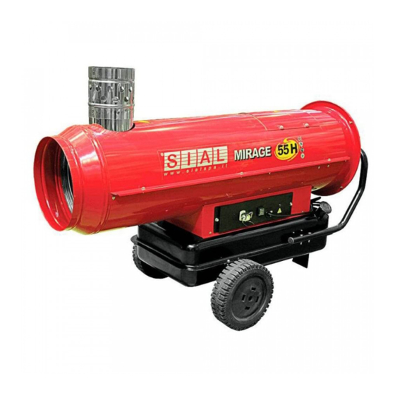
MOBILE (OIL- OR KEROSENE-FIRED) EMERGENCY AIR HEATERS
MIRAGE - TORNADO
SIAL S.p.A
C.so Inghilterra, 15 - 12084 MONDOVI' (CN)
Tel. 0174 560611 fax. 0174 481086
Website
www.sialspa.it
e-mail: tec.com@sialspa.it
Copyright
No section of this document can be reproduced in any form or processed by means of electronic systems, copied or distributed
without written permission by SIAL S.p.A. The translation into other languages is also allowed only under written permission
by SIAL S.p.A. The use of this document is restricted to SIAL servicing centers and to distributors of SIAL products. This
manual is not intended for end users.
Technical changes
SIAL S.p.A. has the right to modify any instruction, description and specification contained in this document without prior
notice.
1
Advertisement
Table of Contents

Related Manuals for SIAL TORNADO 67


Summarization of Contents
OPERATIONAL DIAGRAMS AND SEQUENCES
1.1 Indirect-Fired Heaters with Flue
Diagram illustrating indirect-fired heaters with flue components.
1.2 Direct-Fired Heaters without Flue
Diagram illustrating direct-fired heaters without flue components.
1.3 Operational Sequence
Timing diagram and explanation of the heater's operational sequence.
1.4 Safety Options in Abnormal Operation
Safety measures and responses to abnormal operation conditions.
FUNCTIONAL DESCRIPTION OF COMPONENTS
2.1 Casing and Frame
Detailed description of the heater's casing and frame structure.
2.2 Fan and Motor Assembly
Description of the fan and motor assembly, including its function.
2.3 Fuel Circuit
Explanation of the heater's fuel circuit components and operation.
2.4 Burner Head and Combustion Chamber
Description of the burner head and combustion chamber.
2.5 Electrical Board
Description of the electrical board and its main parts.
TROUBLESHOOTING AND MAINTENANCE
3.1 Checking Supply Voltage
Procedure for checking the heater's supply voltage.
3.2 Power Cord Check and Replacement
Steps for checking and replacing the power cord.
3.3 Motor Check and Replacement
Procedure for checking and replacing the motor.
3.4 Fan Check and Replacement
Steps for checking and replacing the fan.
3.5 Exhaust Gas Analysis and Air Adjustment
How to perform exhaust gas analysis and adjust combustion air.
3.6 Fuel Tank Cleaning
Instructions for cleaning the fuel tank.
3.7 Oil Filter Check, Clean, Replace
Steps to check, clean, or replace the oil filter.
3.9 Burner Head and Whirl Disc Maintenance
Procedure for checking, cleaning, and replacing the burner head and whirl disc.
3.10 Combustion Chamber Cleaning
Steps for cleaning the combustion chamber.
3.11 Motor/Pump Joint Replacement
Procedure to replace the motor/pump joint.
3.12 Fuel Pump Service
Steps for checking, cleaning, adjusting, or replacing the fuel pump.
3.13 Fuel Solenoid Valve Service
Procedure for checking and replacing the fuel solenoid valve.
3.14 Electrode Service
Steps for checking, cleaning, adjusting, or replacing electrodes.
3.15 High Voltage Cables Service
Procedure for checking and replacing high voltage cables.
3.16 Ignition Transformer Service
Steps for checking or replacing the ignition transformer.
3.17 Fuse Replacement
Procedure for replacing the fuse.
3.18 Flame Sensor Service
Steps for checking, cleaning, or replacing the flame sensor.
3.19 Overheat Thermostat Service
Procedure for checking or replacing the overheat thermostat.
3.20 Burner Control Unit Operation Check
Tests to verify the operation of the burner control unit.
SETTING CHARTS
4.1 Indirect-Fired Heaters Setting Chart
Setting parameters for indirect-fired heaters with flue.
4.2 Direct-Fired Heaters Setting Chart
Setting parameters for direct-fired heaters without flue.
TECHNICAL DATA SHEETS
37 kW Indirect Fired Heater Data Sheet
Technical specifications for the 37 kW indirect-fired oil heater.
55 kW Indirect Fired Heater Data Sheet
Technical specifications for the 55 kW indirect-fired oil heater.
85 kW Indirect Fired Heater Data Sheet
Technical specifications for the 85 kW indirect-fired oil heater.
67 kW Direct Fired Heater Data Sheet
Technical specifications for the 67 kW direct-fired oil heater.
115 kW Indirect Fired Heater Data Sheet
Technical specifications for the 115 kW indirect-fired oil heater.
WIRING DIAGRAMS
4.2 Basic Version Wiring Diagram
Wiring diagram for the basic version of the heater.
Wiring Diagram with Heated Filter and Nozzle Pre-heater
Wiring diagram for models with heated filter and nozzle pre-heater.
Need help?
Do you have a question about the TORNADO 67 and is the answer not in the manual?
Questions and answers