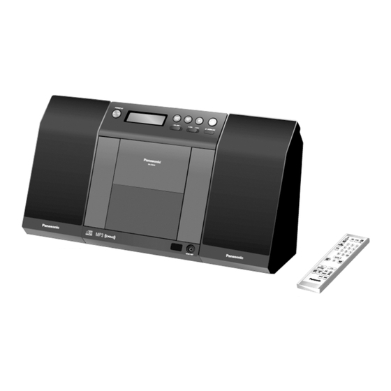
Panasonic SA-EN37 Service Manual
Hide thumbs
Also See for SA-EN37:
- Operating instructions manual (9 pages) ,
- Operating instructions manual (9 pages)
Table of Contents
Advertisement
Specifications
n AMPLIFIER SECTION
FTC OUTPUT POWER both channel driven simultaneously
10% total harmonic distortion (THD)
1 kHz
RMS OUTPUT POWER both channel driven simultaneously
10% total harmonic distortion (THD)
1 kHz
Output impedance
HEADPHONE
MUSIC PORT
Phone Jack
Terminal
Music Port Jack
Terminal
n TUNER SECTION
Frequency range
FM
AM
n CD SECTION
Disc played [8cm (3") or 12cm (5")]
(1) CD-Audio (CD-DA)
(2) CD-R/RW (CD-DA, MP3)
(3) MP3
2.8 W per channel
3 W per channel
16 W to 32 W
12 kW
3.5 mm stereo
3.5 mm stereo
87.9 MHz to 107.9 MHz (200 kHz)
87.5 MHz to 108.0 MHz (100 kHz)
520 kHz to 1710 kHz (10 kHz)
SC-EN37P
Colour
(K)... Black Type
System
SC-EN37P-K
Main Unit: SA-EN37P-K
Speakers: SB-EN37AP-K (L) & SB-EN37P-K (R)
Sampling frequency
CD
MP3
Bit rate
MP3
Decoding
Pick up
Wavelength
Laser power
Audio Output (Disc)
Number of channels
Frequency response
Wow and flutter
Digital filter
D/A converter
n GENERAL
Power supply
Power consumption
Dimension (W x H X D)
Mass
With speakers
Without speakers
n SPEAKER SECTION
© 2007 Matsushita Electric Industrial Co. Ltd.. All
rights
reserved.
distribution is a violation of law.
ORDER NO. MD0703021CE
CD Stereo System
44.1 kHz
32 kHz, 44.1 kHz, 48 kHz
32 kbps to 384 kbps
16/20/24 bit linear
CLASS 1
2 channel
20 Hz to 20 kHz (+1, -2 dB)
Below measurement limit
MASH (1 bit DAC)
AC 120 V, 60 Hz
220mm x 236mm x 146 mm
(8 21/32" x 9 9/32" x 5 3/4")
3.965 kg (8.75 lbs)
1.75 kg (3.86 lbs)
Unauthorized
copying
A6
785 nm
8
30 W
and
Advertisement
Table of Contents

Related Manuals for Panasonic SA-EN37


Summarization of Contents
Product Specifications
Amplifier, Tuner, CD, General, and Speaker Details
Details output power, impedance, frequency ranges, disc compatibility, and general unit specs.
General Safety Precautions
Servicing Safety Guidelines
Outlines general safety procedures for servicing and handling electrical equipment.
Leakage Current Testing Procedures
Describes methods for checking leakage current (cold and hot checks).
Repair Precautions and Safety Information
Fuse Replacement and Protection Circuitry
Provides warnings for fuse replacement and explains protection circuitry.
Pre-Repair Safety and Safety Parts
Advises on precautions before repairs and identifies critical safety components.
Laser Diode and Traverse Unit Handling
Laser Diode Safety Precautions
Warns about laser safety and precautions when working with the optical pickup.
Traverse Unit Handling Precautions
Provides instructions for safely handling the traverse unit, especially the laser diode.
Lead Free Solder and Accessories
Lead Free Solder Service Cautions
Details service cautions related to lead-free solder usage.
Included Accessories
Lists and illustrates the included accessories.
Operation Procedures
Remote Control and Main Unit Operations
Explains how to operate the unit using the remote control and main unit buttons.
Self-Diagnosis and Special Modes
Service Mode Overview and Operations
Summarizes various service modes and their key operations for diagnostics.
Error Code Troubleshooting
Mechanism Error Code Table
Provides a table of error codes, diagnosis, and automatic FL display.
Assembling and Disassembling
General Cautions and Disassembly Index
Important safety cautions and an index for assembly and disassembly procedures.
Disassembly Flow Charts
Main and Speaker Unit Disassembly Flow
Visual guide for disassembling the main unit and speaker units.
PCB and Component Locations
Main Unit PCB Locations
Illustrates the placement of key components in the main unit.
Speaker Unit PCB Locations
Shows component layout specifically for the SB-EN37A speaker.
Cabinet and Port PCB Disassembly
Rear Cabinet and D-Port PCB Removal
Detailed steps for removing the rear cabinet and D-Port PCB.
Main and Switch PCB Disassembly
Main, Sensor, Tuner PCB Removal
Steps for removing main, sensor, and tuner PCBs.
Switch PCB and Traverse Unit Removal
Steps for removing switch PCB and traverse unit.
Power Switch, Tact Switch, and Traverse Cover Procedures
Power Switch & Tact Switch PCB Removal
Steps for removing power switch and tact switch PCBs.
Traverse Cover Replacement
Procedure for replacing the traverse cover.
Service Tools and Positions
Service Fixture and Tools List
Lists required service fixtures and tools for maintenance.
General Service Positions
Outlines general procedures for connecting and checking the unit during service.
Other PCB Check and Repair
Main, Sensor, Tuner PCB Repair
Details steps for checking and repairing main, sensor, and tuner PCBs.
Power Switch, Tact Switch, CD Block Repair
Details steps for checking and repairing power, tact switch, and CD block.
Voltage and Waveform Charts
Main PCB Voltage Chart
Lists reference voltages for various points on the main PCB in different modes.
Waveform Chart Examples
Illustrates typical waveforms at key ICs during operation.
Block Diagrams
CD Servo, Tuner, and Main Block Diagrams
Illustrates functional blocks of CD servo, tuner, and main unit circuits.
Transformer, Sensor, D-Port Block Diagrams
Illustrates functional blocks of transformer, sensor, and D-Port circuits.
Panel, D-Port, and LED Circuit Schematics
Panel and D-Port Circuit Schematics
Schematic diagrams for the panel and D-Port circuits.
Switching Circuit Schematics
LED, Power, Tact Switch, Switch Schematics
Schematics for LED, power, tact switch, and general switch circuits.
Motor, Sensor, Transformer Circuit Schematics
Motor, Sensor, Transformer Circuit Schematics
Schematic diagrams for motor, sensor, and transformer circuits.
Printed Circuit Board Layouts
CD Servo and Tuner PCB Layouts
Visual layout of the CD Servo and Tuner printed circuit boards.
Switch, Motor, Sensor, Transformer PCB Layouts
Switch, Motor, Sensor PCB Layouts
Visual layouts for Switch, Motor, and Sensor printed circuit boards.
Transformer PCB Layout
Visual layout of the Transformer printed circuit board.
IC Terminal Functions
IC801 Terminal Functions
Details the pin functions for IC801 (Servo Processor, DSP, D/A Converter).
Need help?
Do you have a question about the SA-EN37 and is the answer not in the manual?
Questions and answers