Table of Contents
Advertisement
• FAST SHIPPING AND
DELIVERY
• TENS OF THOUSANDS OF
IN-STOCK ITEMS
• EQUIPMENT DEMOS
• HUNDREDS OF
MANUFACTURERS
SUPPORTED
• LEASING/MONTHLY
RENTALS
• ITAR CERTIFIED
SECURE ASSET SOLUTIONS
Artisan Technology Group
new and certified-used/pre-owned equipment
SERVICE CENTER REPAIRS
Experienced engineers and technicians on staff
at our full-service, in-house repair center
View
Instra
REMOTE INSPECTION
SM
Remotely inspect equipment before purchasing with
www.instraview.com
our interactive website at
Contact us:
(888) 88-SOURCE | sales@artisantg.com | www.artisantg.com
is your source for quality
WE BUY USED EQUIPMENT
Sell your excess, underutilized, and idle used equipment
We also offer credit for buy-backs and trade-ins
www.artisantg.com/WeBuyEquipment
LOOKING FOR MORE INFORMATION?
Visit us on the web at
information on price quotations, drivers, technical
specifications, manuals, and documentation
www.artisantg.com
for more
Advertisement
Table of Contents

Related Manuals for Haake N6

Summarization of Contents
Key to Symbols
Symbols Used in this Manual
Explains symbols for warnings, remarks, and operating steps within the manual.
Symbols on the Unit (Front)
Details symbols on the front panel: caution, on/off positions, reset, and menu selection.
Value Alteration
Describes how to alter digits for temperature or time displays using arrow keys and confirmation.
Menu Selection
Explains how to navigate and select menu points using arrow keys and the ENTER key.
Symbols on the Unit (Rear)
Illustrates symbols for tap water cooling and pump connections on the rear of the unit.
Symbols on the Display
Details display symbols indicating unit status like START, ALARM, heating/cooling activity, and Fuzzy control.
Menu Tree
Visual representation of the unit's menu structure, showing navigation paths for various functions.
Safety Notes
General Safety Warnings
Highlights general risks, proper usage, user responsibility, and essential precautions for safe operation.
Handling Hot Parts and Liquids
Warns about hot surfaces, risks of burns, and precautions for handling heat transfer liquids and the unit.
Electrical Safety and Protection Ratings
Details electrical protection measures, grounding, IP ratings, and precautions against water and dust.
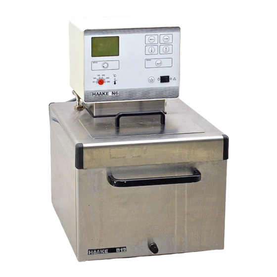
Unit Description
Safety Features
Explains the comprehensive safety system based on the 'single fault' concept for preventing hazardous situations.
Safety Class 2 According to DIN 12879
Describes safety class 2 compliance and how safety elements trigger to ensure a stable, safe condition.
Applications
Outlines the unit's use as an open-bath circulator and a heating circulator for various temperature control tasks.
Temperature Ranges
Defines the working and operating temperature ranges and notes on using tap water for cooling.
Unpacking and Setting Up
Transportation Damage and Contents
Instructions on checking for transportation damage, reporting issues, and listing the package contents.
Ambient Conditions and Resting Time
Specifies required ambient conditions and the mandatory 24-hour resting time for refrigerated circulators.
Ventilation Requirements
Emphasizes keeping ventilation grids unobstructed to ensure proper air circulation and unit performance.
CE Sign Information
Details the CE sign conformity with EU directives for electromagnetic compatibility and low voltage.
Mounting onto Bath Bridges
Provides step-by-step instructions for mounting the unit onto bath bridges, including safety precautions.
Functional Elements
Front Panel (F and N)
Identifies and describes the functions of the control elements on the front panel of the unit.
Rear Panel (F and N)
Details the connections and ports located on the rear panel of the unit.
Bath Vessel B5 (Example)
Illustrates and labels the components of the bath vessel B5, used as an example for B7 and B12 models.
Refrigerated Bath C25 (Example)
Illustrates and labels the components of the refrigerated bath C25, used as an example for various models.
Hoses
Connecting Hoses
Instructions on connecting hoses for circulation, including recommendations for optimal setup and safety.
Selecting Hoses
Guidance on choosing appropriate hoses based on application and temperature requirements.
Plastic and Rubber Hoses
Details specifications and order numbers for various types of plastic and rubber hoses.
Metal Hoses
Describes insulated metal hoses, their specifications, and safety precautions for use at high temperatures.
Tap Water Cooling
Explains connection and usage of tap water cooling for units without refrigeration, including flow rate adjustments.
External Cooling Devices
Introduces flow-through coolers for rendering the circulator independent of tap water.
Pressure Pump Connections
Details connections for internal bath, external closed, and external open systems using the pressure pump.
Filling with Bath Liquid
Recommended Bath Liquids
Lists and describes recommended bath liquids, including distilled water, water with antifreeze, and SIL180.
Connecting Up
Connecting to the Mains
Instructions for connecting the unit to grounded mains sockets, checking voltage, and ensuring proper connection.
Checking the Liquid Circuit
Procedure to verify the liquid circuit before switching on, ensuring ports are connected or blocked.
Changing the Mains Plug
Guidance for changing the mains plug, emphasizing it must be done by qualified personnel.
Fuses on the Unit
Information on automatic thermally-triggered fuses, how to handle a triggered fuse, and when to seek servicing.
Configuration
Interface RS 232C Configuration
Steps to configure the RS232C interface, including selecting COMPUTER mode.
Analog Interface Configuration
Details how to configure the optional analog interface, selecting COMPUTER or ANALOG modes.
Language Selection
Instructions on how to select the display language via the SETUP-1 menu.
Temperature Display Settings
Describes how to set the temperature standard (°C, °F, K) and display resolution.
Autostart Function
Explains the autostart feature, its behavior during power failures, and associated risks.
Resetting Unit Parameters
Details the reset function, differentiating between TOTAL and PARTIELL resets.
Display Contrast Adjustment
Guide on adjusting the display contrast using the LCD-CONTR function.
Acoustic Signal Setting
Instructions for enabling or disabling the acoustic signal that sounds after a program run.
Version Number Information
Specifies where to find software and Fuzzy control version numbers for servicing or inquiries.
Operation Status Monitoring
Explains how to check the operating status of alarm circuits, control modes, and interfaces.
Operating the Circulator
Switching the Unit On
Procedure for switching on the unit, checking initial display, and starting operations.
Internal vs. External Control Sensors
Guide on selecting and working with internal or external control sensors and their associated modes.
Working with or Without Cooling
Instructions on activating or deactivating the cooling aggregate based on desired set temperatures.
Setting the Desired Set Temperature
Detailed steps for setting the target temperature using the T-SELECT and SETPOINT functions.
Setting the RTA System Correction Value
Explains how to determine and set the RTA system correction value for accurate temperature control.
Setting Temperature Limit Values
Describes how to set high and low temperature limits to restrict the operating range for safety.
Controlling Heating and Cooling Cycles
Explains how heating and cooling cycles are indicated and controlled, including full and partial cooling capacity.
Excess Temperature Protection
Excess Temperature Protection Dial
Explains the dial's purpose for preventing uncontrolled heating and ensuring proper cut-off point settings.
Setting the Excess Temperature Cut-off
Step-by-step guide to setting the excess temperature cut-off point, crucial for safety and protection.
Testing the Cut-off Point
Procedure to test the effectiveness of the set excess temperature cut-off point.
Fault Displays and Troubleshooting
Excess Temperature Fault
Describes the 'Excess temperature' alarm, its causes, and recommended actions.
Low Liquid Level Cut-off Fault
Explains the 'Low liquid level' alarm, its triggers, and troubleshooting steps.
Pump or Motor Overloading Fault
Details the 'Pump or motor overloading' alarm, potential causes, and reset procedures.
Sensor Breakage or Short Circuit Fault
Covers faults related to internal or external sensor issues (breakage, short circuit, REF message).
Undefined and External Faults
Addresses 'Undefined fault' and 'External fault RS232C', outlining potential causes and checks.
Cooling Unit Connection Errors
Lists various 'Error in connection with cooling units' messages and their corresponding troubleshooting steps.
Fault Elimination and Fuzzy Control
Explains how to confirm fault elimination and details specific fault displays related to Fuzzy control identification.
Testing Safety Features
Testing Excess Temperature Protection
Procedure for testing the excess temperature protection mechanism at regular intervals.
Testing Low Liquid Level Protection
Method for testing the low liquid level protection feature to ensure proper shut-off.
External Connections
Interface RS232C
Reference to chapter 18 for detailed information on the RS232C interface.
Remote Alarm Connection
Describes the potential-free contact for remote alarm signaling and its pin assignment.
External Pt100 Sensor
Details requirements for external Pt100 sensors, including shielding and pin assignment.
I/O Port (Optional)
Information on the optional I/O port for analog signals, referring to appendix for details.
Shielded Cables
Emphasizes the importance of using shielded cables and high-quality connections for electromagnetic compatibility.
RS232C Interface
Connecting to a Computer
Explains the pin assignment for connecting the circulator to a computer via 9-pin or 25-pin sockets.
Interface Parameters
Details how to set interface parameters like baud rate, data bits, and parity via the circulator's menu.
External Unit Requirements
Specifies that only EN 60950 tested units should be connected to the circulator's interface.
Setting Desired Set Value via Computer
Describes how setting the set value via computer affects circulator operation, especially after connection interruption.
Watchdog Functionality
Explains the watchdog function for generating alarms and its timeout period settings.
Correction Value Setting via Computer
Details how setting the correction value via computer impacts circulator operation.
Controlling the Circulator
Outlines methods for controlling the circulator via BASIC programs or Windows-Terminal.
Controlling via BASIC Program
Provides a sample BASIC program structure for activating circulator commands via the interface.
Controlling via Windows-Terminal
Instructions on configuring and using Windows-Terminal for controlling the circulator.
Sets of Commands
Describes the three available sets of commands (Standard, Extended, NAMUR) for communication.
Operating Status and Error Messages
Details how to call up operating status and interpret error messages using state flags.
Ramp Program Definition via PC
Explains how to define temperature ramp programs using the PC and RS232C interface.
Maintenance
Cleaning the Liquefier Fins
Instructions for cleaning the liquefier fins to maintain cooling capacity, including frequency and procedure.
Discarding the Unit
Information on the proper disposal of the unit, noting the presence of coolants and authorized personnel requirements.
Technical Specifications
Bridge Circulators Specifications
Presents technical specifications for Bridge Circulator models F6-H51 and N6-H51.
Heating Circulators Specifications
Lists technical specifications for Heating Circulator models F6-B5, N6-B7, and N6-B12.
Refrigerated Circulators Specifications
Provides technical specifications for various Refrigerated Circulator models (C25, C35, C40, C20, C41, C50).
Fuse Values
Tabulates fuse values for different unit types, mains voltages, and locations (rear panel, in unit).
Optional I/O Board
Installation of I/O Board
Step-by-step guide for installing the optional I/O board, emphasizing trained personnel and safety.
Pin Assignment
Details pin assignments for signal input (reference, current) and signal output (measuring value).
Input Configuration
Guides on configuring voltage and current inputs, including setting values and adjusting input parameters.
Output Configuration
Instructions for configuring voltage and current outputs to monitor actual temperature values.
Simultaneous Operation and Control
Covers simultaneous input/output, stopping I/O, timer-based starting, and fault display F01.
Need help?
Do you have a question about the N6 and is the answer not in the manual?
Questions and answers