Table of Contents
Advertisement
Sistema elettronico di controllo per piani magnetici
Electronic control system for magnetic chucks
Système électronique de commande pour des plateaux magnétiques
Elektronisches Steuersystem für Magnetplatten
Sistema electrónico de control para planos magnéticos
ST100
ST200
Manuale uso e manutenzione
Instruction and maintenance manual
Manuel d'utilisation et d'entretien
Betriebs- und Wartungsanleitung
Manual de uso y mantenimiento
Nr. 50 100 7816
Advertisement
Table of Contents

Related Manuals for TECNOMAGNETE ST200 Series

Summary of Contents for TECNOMAGNETE ST200 Series
- Page 1 Sistema elettronico di controllo per piani magnetici Electronic control system for magnetic chucks Système électronique de commande pour des plateaux magnétiques Elektronisches Steuersystem für Magnetplatten Sistema electrónico de control para planos magnéticos ST100 ST200 Manuale uso e manutenzione Instruction and maintenance manual Manuel d’utilisation et d’entretien Betriebs- und Wartungsanleitung Manual de uso y mantenimiento...
-
Page 2: Table Of Contents
INDEX Page Page GENERAL NOTES CONNECTION TO ........32 Overview.of.the.company......32 TECNOMAGNETE MODULE ....48 Importance.of.the.manual......33 Installation.of.miller.ST100......48 Storing.the.manual........33 Installation.of.grinder.ST100.......48 Conventions..........33 Installation.of.miller.ST200......49 Definition.of.symbols........33 Installation.of.grinder.ST200.......50 Personnel.responsible.for.operations..33. Trained.personal..........34 ORDINARY USE ........51 Individual.protection.means......34. ST100............51 General.safety.precautions......34 ST200............51 1.10 Behavior.during.emergency.situations..34 1.11 Limitations...........34 ANALYSIS OF RESIDUAL RISKS ..52... -
Page 3: General Notes
For.further.information.on.the.system,.you.can.con- The.permanent-electro.magnetic.systems.manufac- tact. TECNOMAGNETE’s. technical. support. at. any. tured. by. TECNOMAGNETE. are. able. to. produce. all. time. the. magnetic. force. required. both. to. clamp. and. lift. The. descriptions. and. illustrations. provided. in. this. work.pieces,.thus.eliminating.the.need.of.using.elec- manual.are.for.reference.only. -
Page 4: Importance.of.the.manual
1.5 Definition of symbols 1.2 Importance of the manual All.information.related.to.safety.is.highlighted.in.bold. A.copy.of.this.manual.must.always.be.made.availa- All.warnings.that.draw.the.attention.of.operators.on. ble.to.the.operators.responsible.for.the.installation,. operations.that.may.be.hazardous.in.terms.of.safety. operation.and.maintenance.of.the.controller.in.order. or.health.or.that.may.cause.physical.injuries,.if.the. to.allow.them.to.carry.out.all.the.required.operations. applicable. instructions. are. not. followed,. are. high- in.compliance.with.the.instructions.provided.in.the. lighted. in. red. and. marked. with. the. following. sym- manual. bol: A. full. compliance. with. the. instructions. provided. in. this.manual.is.an.essential.requirement.to.be.able.to. -
Page 5: Trained.personal
TECNOMAGNETE S.p.A. shall not be responsible for damages caused to people or equipment originating from the failure to follow applicable safety provisions and to comply with the instruc- tions given below. -
Page 6: Improper.or.non.permitted.use
• Use suitable equipment. • Comply with all the instructions provided. • Fix the unit onto a stable surface. • Contact TECNOMAGNETE S.p.A. in case of doubt to determine whether a specific opera- tion is permitted. 1.13 Nameplate data The.controller.is.fitted.with.an.identification.label.in. -
Page 7: Transportation And Handling
Upon. receipt,. customers. should. verify. that. the. packaging. and. the. material. inside. it. has. not. been. damaged. (unless. otherwise. instructed. by. TECNOMAGNETE.S.p.A.).in.order.to.ensure.that.the. unit.has.not.been.damaged.during.transport.and.that. the.material.supplied.complies.with.order.specifica- tions..Visible.transport.damages.should.be.immedi- ately. reported. to. TECNOMAGNETE. S.p.A.. and. the. forwarding.agent. 2.4 Storage The. unit. should. always. be. throughly. cleaned. and. adequately.protected.when.stored.for.long.periods. of.time. ATTENTION Disconnect.the.controller.from.the.magnetic.chuck. -
Page 8: Description Of The System
rate.a.maximum.power.of.4kVA..For.example,.if.the. DESCRIPTION available. voltage. is. 400V,. a. transformer. with. a. 400/230.transformation.ratio.is.required. OF THE SYSTEM ATTENTION! .Control.units.can.be.moved.only. when.controls.are.not.powered. 3.1 Description of the controllers ST. is. an. innovative. electronic controller for networked chucks. designed. for. milling. and. grin- ding.operations. The.sections.that.follow.provide.information.on.the. size. and. the. basic. characteristics. of. the. available. models: •... -
Page 9: Model.st200X
The. maximum. power. of. controller. ST200X. is. ap- 3.3 Model ST200X proximately.25kW.per.discharge.if.the.single.phase. power. supply. is. 400V,. 15kW. for. power. supplies. of. 230V.and.30kW.for.power.supplies.of.480V..The.ab- The.rated.operating.voltage.of.this.controller.varies. sorbed.current.is.impulsive.with.a.cycle.time.around. according.to.the.type.of.magnetic.chuck.to.which.it. a. few. hundreds. of. milliseconds. (approximately. 1. is.connected. second.per.discharge). The.control.push-button.is.external,.but.can.also.be. integrated.into.the.controller. ST200X. controllers. are. suitable. to. power. single. The.control.electronics.are.enclosed.in.a.metal.hous- chucks. -
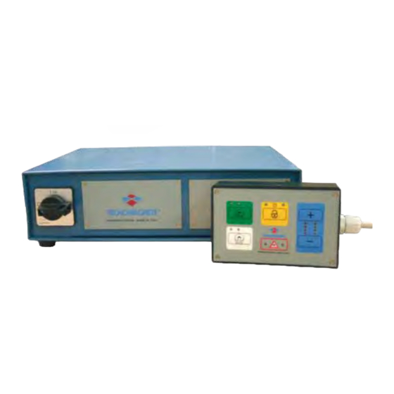
Page 10: Control.push-Buttons.for.st.controllers
3.4 Control push-buttons for ST controllers ST.controllers.can.be.connected.to.the.push-button. panels.described.below. 3.4.1 ST100 (basic version), ST200 (basic version) This. push-button. panel. is. the. base. model. used. to. control.milling.chucks. It.is.fitted.with.the.following.three-buttons: •.Magnetization.. FULL-MAG, PUSH-BUTTON PANEL •.Demagnetization.. DEMAG, A ➜ FULL-MAG.button •.Enabling.. ENABLE. B ➜ ENABLE.button The.ENABLE.button.is.used.together.with.the.mag- C ➜... - Page 11 3.4.2 ST100 (version with 2 levels), If.a.cycle.is.active,.the.only.LED.that.is.on.is.the.one. ST200 (version with 2 levels) related.to.the.cycle,.while.all.the.others.are.off. At.the.end.of.the.cycle,.the.only.visual.indication.that. To.be.able.to.use.different.levels.of.magnetization,.it. is.on.is.the.one.related.to.the.new.system.status. is. possible. to. replace. the. push-button. panel. de- FULL-MAG.and.DEMAG.indicator.lights.are.always. scribed.above.with.a.2-level.model.that.enables.to. on;. MAG-1L. and. MAG-2L. flash. only. during. partial. control.milling.and.grinding.chucks.. magnetization.cycles. This. push-button. panel. has. the. following. five. but- tons: FULL-MAG,.
- Page 12 3.4.3 ST200 (model with 7 levels) If.a.cycle.is.active,.the.only.LED.that.is.on.is.the.one. related.to.the.cycle,.while.all.the.others.are.off. To.be.able.to.use.several.levels.of.magnetization,.it.is. The.FULL-MAG.and.DEMAG.indicator.lights.are.al- possible.to.replace.the.basic.push-button.panel.with. ways.on.and.flash.during.partial.magnetization.cy- a. 7-level. model. that. enables. to. control. milling. and. cles.only. grinding.chucks. This. push-button. panel. has. the. following. five. but- tons: MAG, •..Magnetization.. •..Increase.of.magnetization. . level..•..Reduction.of.magnetization. . level.. –...
- Page 13 3.4.4 ST200 CH-ENABLE This.push-button.panel.can.be.used.when.you.need. to.select.different.discharge.levels.for.the.magnetic. chucks,.i.e..enable.or.disable.the.desired.discharge. The.push-button.panel.can.be.used.in.combination. with.a.push-button.and.LED.to.manage.selections. It.has.four.buttons.that.enable.to.select/deselect.the. desired.discharge.channel..The.status.of.the.channel. is.shown.by.the.corresponding.LED. After. you. have. selected. the. discharge. sequence,. you. can. also. specify. which. discharges. have. to. be. carried.out.with.a.full.or.partial.magnetization.and/or. select.them.with.the.appropriate.buttons.(CH1, CH2, CH3.and.CH4). PUSH-BUTTON PANEL The. status. LEDs. are. off. when. the. corresponding. A.
-
Page 14: Installation
Tecnomagnete. modules. with. lower. or. laws. concerning. electric. safety.. Therefore,. it. is. es- higher. ratings.. To. use. different. voltages,. install. a. -
Page 15: Connecting St100 Controllers To The Power Supply
+. neutral. distribution. network. that. supplies. the.tool.machine.used..If.the.voltage.required.for.the. controller.is.not.available,.install.a.power.transformer. with.a.rating.suited.for.the.magnetic.chuck. BLACK BROWN Single-phase power supply YELLOW/GREEN 4.2.2 Power cable TECNOMAGNETE. supplies. a. suitable. multi-pole. power.cable.with.a.standard.length.of.two.meters,. BLACK which.prevents.overheating.problems.and.a.voltage. BROWN drop.within.the.rating.of.the.TECNOMAGNETE.mod- YELLOW/GREEN ule,.if.used.in.ordinary.operating.conditions. Before. using. longer. cables,. always. make. sure. that. the. cable. section. used. guarantees. a. voltage. drop. -
Page 16: Enabling
4.3.2 Power cable ENABLING TECNOMAGNETE. supplies. a. suitable. multi-pole. power.cable.with.a.standard.length.of.four.meters,. which.prevents.overheating.problems.and.a.voltage. 5.1 ST100 drop.within.the.rating.of.the.TECNOMAGNETE.mod- ule,.if.used.in.ordinary.operating.conditions. ST100.controllers.are.not.fitted.with.a.specific.ena- Before. using. longer. cables,. always. make. sure. that. bling.device,.which.may.however.be.ordered.as.op- the. cable. section. used. guarantees. a. voltage. drop. tional.(see.Chapter.6.1). below.1%. Ordinary.operating.conditions.are.intended.as.inter- mittent.working.cycles,.with.intervals.of.at.least.one. 5.2 ST200 minute.between.two.enabling.cycles. -
Page 17: Optional Components
•.30V.voltage,.1A.current •.110V.voltage,.0.3A.current The.function.of.available.contacts.is.described.be- low. It.is.generally.advisable.to.use.an.auxiliary.relay. Before.using.other.models.of.start.systems,.contact. TECNOMAGNETE.S.p.A..for.assistance. 6.2 Push-button panels of models ST100 and ST200 ST100.controllers.can.be.fitted.with.an.optional.two- level. push-button. panel. for. milling. and. grinding. chucks. Model.ST200.can.instead.be.fitted.with.an.optional. 2-level. push-button. panel. for. milling. and. grinding. - Page 18 Name Direction Description SW.Mag Magnetization.button SW.Demag Demagnetization.button SW.Level.+ Button.that.increases.the.magnetization.level SW.Level.- Button.that.decreases.the.magnetization.level Abilit.PLC Enabling.input.for.PLC.management Input.Enable Input-Enable.input Not.connected Not.connected. Not.connected. Level.1 1st.level.magnetization.output Level.2 2nd.level.magnetization.output Level.3 3rd.level.magnetization.output Level.4 4th.level.magnetization.output Level.5 5th.level.magnetization.output Level.6 6th.level.magnetization.output Level.7 7th.level.magnetization.output Level.8 8th.level.magnetization.output Normally.open.common.contact.Out-Abilit Normally.open.contact.Out-Abilit Wait Output,.cycle.in.progress Alarm Alarm.output Not.used Not.used Out2...
-
Page 19: Tecnomagnete Module
CONNECTION TO THE TECNOMAGNETE MODULE 8.1 Installation of miller ST100 Magnetic. module Connector Discharge.cable Controller Power.supply 8.2 Installation of grinder ST100 Magnetic. module Cable.tie Discharge.cable Controller Power.supply Instruction and maintenance manual... -
Page 20: Installation.of.miller.st200
.Power.supply 8.3 Installation of miller ST200 .Push-button.panel.. .CH.ENABLE.push-button.panel. .Enabling .Discharge .Discharge .PLC.interface .ON/OFF .4.PIN.connector .7.PIN.connector .Junction.box Controller Controller Installation of Installation of ST200 ST200 1 chuck 3 chucks Magnetic.chucks . -
Page 21: Installation.of.grinder.st200
.Power.supply 8.4 Installation of grinder ST200 .Push-button.panel. .CH.ENABLE.push-button.panel.(optional). .Enabling .Discharge .Discharge G.Discharge .Discharge .PLC.interface .ON/OFF Installation of Installation of Controller Controller 1 chuck 3 chucks ST200 ST200 Magnetic.chucks Magnetic.chuck ... -
Page 22: Ordinary Use
To.start.the.ST100.controller,.follow.this.procedure: 8).. Verify. that. the. LED. above. the. MAG. button. switches.on. 1).. Connect. the. discharge. cable. TECNOMAGNETE’s.module. 9).. Verify.that.the.module.is.magnetized. 2) . Connect.the.plug.of.the.power.cable.to.the.230V. 10). If.the.discharge.cable.has.been.removed,.start. electric. socket. and. connect. the. connector. to. the. working. cycle. remembering. to. close. the. the.magnetic.chuck,.where.available. connector.and.check.the.status.of.the.chuck.at. -
Page 23: Analysis Of Residual Risks
ATTENTION • As the controller is designed to be used to All. maintenance. operations. must. be. performed. by. control TECNOMAGNETE modules that are qualified.personnel.only.(see.Chapter.1.7).. generally installed on tool machines, it is es- While. performing. maintenance. operations,. always. -
Page 24: Weekly.maintenance
11.6 Extraordinary maintenance Maintenance.operations.not.specifically.described.in. this. manual. are. considered. extraordinary. mainte- nance.and.must.be.carried.out.by.qualified.person- nel. specifically. authorized. by. TECNOMAGNETE. S.p.A... 11.7 Information on extraordinary reparation and maintenance The.sections.that.follow.provide.a.dimensional.lay- out.and.assembly.instructions.for.each.chuck.model. to.simplify.troubleshooting. TECNOMAGNETE. S.p.A.. can. be. contacted. at. any. time.for.further.information.or.queries.regarding.the. operation.and.maintenance.of.the.controller. Instruction and maintenance manual... -
Page 25: Troubleshooting And Corrective Actions
TROUBLESHOOTING AND DECOMMISSIONING AND CORRECTIVE ACTIONS DISPOSAL This. section. provides. information. designed. to. help. 13.1 Decommissioning operators.to.troubleshoot.and.correct.the.problems. that.may.arise.during.the.use.of.the.equipment. The. unit. should. always. be. disconnected. from. the. For.information.on.how.to.solve.problems.related.to. power.supply.and.disassembled.from.the.tool.ma- electric.issues,.see.the.enclosed.diagrams.and.the. chine.on.which.it.is.installed.if.it.is.not.likely.to.be. operation. and. maintenance. manuals. supplied. with. used.for.extended.periods.of.time. the.controller. All.reparation.on.electric.components.must.be.car- 13.2 Dismantling ried. -
Page 26: Warranty And Technical Support
•. If.the.customer.fails.to.make.the.payments.at.due. 14.1 Warranty terms and conditions time.or.fulfill.contractual.obligations •. If. unauthorized. reparations. or. alterations. are. made TECNOMAGNETE. products. are. guaranteed. for. 36. months.from.the.date.of.manufacture.except.where. •. If. the. serial. number. has. been. tampered. with. or. otherwise.indicated.in.writing..Said.warranty.covers. deleted all. defects. of. materials. and. workmanship.. Faulty. - Page 27 Tel..+49.6103.750730. TECNOMAGNETE R.O. Fax.+49.6103.7507311 Pudong.Lujiazui.Dong.road.161,. kontakt@tecnomagnete.com SHANGHAI-.Room.2110.-.PC:.200120. Tel:.+86.21.68882110 PORTUGAL Fax.+.86.21.58822110 SOREP info@tecnomagnete.com.cn.. Rua.Nova.Da.Comeira,.4 2431-903.MARINHA.GRANDE.(PORTUGAL) SINGAPORE - SOUTH-EAST ASIA - ASIA PACIFIC Tel..+351.244572801 TECNOMAGNETE Singapore R.O. Fax.+351.244572801 101.Thomson.Road.26.-.02.United.Square geral@sorep.co.pt Singapore.307591 Tel:.+65.6354.1300.. SPAIN Fax.+65.6354.0250 DTC TECNOLOGIA infosgp@tecnomagnete.com Poligono.Osinalde.-.Zelai.Haundi,1 20170.USURBIL.(SPAIN) Tel..+34.943.376050 Fax.+34.943.370509 dtc@dtctecnologia.com...
-
Page 28: Delaration Of Conformity
Tecnomagnete S.p.A. Sede Legale in Milano, P.le Cadorna 10 Sede Operativa ed Amministrativa in Lainate (Mi), via Nerviano 31 - 20020 Italy DICHIARAZIONE DI CONFORMITA’ DELARATION OF CONFORMITY LA SOTTOSCRITTA DITTA: THE FIRM TECNOMAGNETE SPA erviano 20020 – LAINATE (MI) ITALY DICHIARA SOTTO LA PROPRIA RESPONSABILITÀ... - Page 29 • IT • SE • CN TECNOMAGNETE S.p.A. TECNOMAGNETE AB TECNOMAGNETE Shanghai R.O. 20020 Lainate (MI) Gustafsvagen 16 Pudong Lujiazui Dong road 161, Via Nerviano 31 633 46 Eskilstuna Room 2110 - PC: 200120 Tel. +39 02.937.591 Tel. +46 016 132 200 Tel.
Need help?
Do you have a question about the ST200 Series and is the answer not in the manual?
Questions and answers