
Related Manuals for Lupus Electronics XT2


Summary of Contents for Lupus Electronics XT2
- Page 1 XT 1 Plus, XT2 (Plus), XT3 Alarm panel User Manual Manual version 1.3 (Firmware 0.0.3.0K)
-
Page 2: Table Of Contents
Table of content Table of content ............................. 2 Introduction ..............................7 Difference of the alarm panels ......................8 Disclaimer ............................9 Important safety information ......................11 If you find defects ..........................12 Designated use ..........................12 The most important chapters for the initial setup ..................13 Putting the LUPUSEC-XT2 (Plus) into operation .................. - Page 3 Cameras ............................81 Capture ............................84 Power consumption ........................85 Temperature history ........................86 Scenarios ............................87 Alarm system ..........................88 Settings ............................88 Siren settings ..........................95 Report ............................100 PIN codes ............................. 105 Settings ..............................107 Network ............................107 E-mail account ..........................
- Page 4 Connecting the 12 / 24 V wireless relay and putting it into operation ......157 1 channel relay ..........................159 Connecting the single channel relay and putting it into operation ........160 1 channel relay ..........................162 Connecting the double channel relay and putting it into operation ......... 163 360°...
- Page 5 Mechanical lock ..........................224 Installing the mechanical lock to the doorframe and putting it into operation ....225 Medical emergency controller ....................... 227 Connecting the medical emergency controller and putting it into operation ....227 Outdoor keypad ..........................229 Connecting the outdoor keypad with tag reader and putting it into operation ....231 Outdoor siren V2 ...........................
- Page 6 Connecting the temperature sensor and putting it into operation ........298 Temperature sensor with display V2 .................... 300 Connecting the temperature sensor and putting it into operation ........300 Temperature sensor with external probe ..................302 Connecting the temperature sensor with external probe and putting it into operation ... 303 Top-hat rail relay ...........................
-
Page 7: Introduction
Introduction Thank you for purchasing the XT alarm panel. Before you start the alarm panel, please take the time to read the following safety and installation information carefully and attentively. This manual is for the alarm panels XT1 Plus, XT2, XT2 Plus, and XT3. Some chapters and/or functions are not available for all models. -
Page 8: Difference Of The Alarm Panels
Difference of the alarm panels Feature LUPUS-XT1 LUPUS-XT2 LUPUS-XT3 Plus (Plus) Chassis Access via LUPUS App. Max. amount of sensors or Smarthome devices. 100% data security: no server, no cloud. All data is stored locally! Second method for alarm notifications via mobile communication (GSM). -
Page 9: Disclaimer
Disclaimer All technical details and descriptions in this manual were compiled with the greatest care. However, Lupus-Electronics cannot entirely exclude mistakes in this manual. Therefore, we do not assume any legal responsibility or liability, which is result of wrong information in this manual. - Page 10 WARNING: TO MINIMIZE THE RISK OF ELECTRIC SHOCK, YOU MUST NOT EXPOSE THIS PRODUCT TO WET AND MOIST CONDITIONS AT ANY TIME. All Lupus-Electronics products are lead-free and meet the requirements stated under the European Directive on the Restriction of Hazardous Substances (RoHS).
-
Page 11: Important Safety Information
Important safety information WARNING The warranty claim will expire in case of damages resulting from the non-observance of this manual. We do not assume any liability for consequential damages. We do not assume any liability for damages to persons and/or material whatsoever, which result from improper handling or noncompliance with the safety instructions. -
Page 12: If You Find Defects
If you find defects If you notice any kind of defect, disconnect the alarm panel from the power supply and contact your retailer or LUPUS-Electronics directly. Any further usage of the system may lead to fire or electric shock! Designated use This alarm panel is intended for property security purposes. -
Page 13: The Most Important Chapters For The Initial Setup
The most important chapters for the initial setup Beginning with the chapter “home menu,” this manual covers the menus of the alarm panel according to the layout of the browser interface. For the initial setup, several of the sub-menus are not important and can be skipped at first. Following the most important chapters for the initial setup are listed: 1. -
Page 14: Putting The Lupusec-Xt2 (Plus) Into Operation
Putting the LUPUSEC-XT2 (Plus) into operation The following pages describe the installation and start-up of the alarm panel systematically. To avoid damages to the system, please observe these instructions in detail and read the manual carefully before you start. Remove the alarm panel from the packaging. Please check immediately after the delivery for possible transportation damages and whether the product’s scope of delivery. -
Page 15: Connecting The Xt1 Plus Alarm Panel
Connecting the XT1 Plus alarm panel 1. You need to install the XT1 Plus at a wall. For the mounting, screws, dowels, and a wall mount are included. Screw the wall mount unto a wall and observe the information given in the chapters “important safety information” and “place of installation”. - Page 16 4. Connect the LAN cable to the alarm panel and then connect it to an internet router. 5. Mount the XT1 alarm panel to the wall mount. Make sure that the alarm panel locks to the wall mount. Description of the connectors: 1.
-
Page 17: Connecting The Xt2 (Plus) Alarm Panel
Connecting the XT2 (Plus) alarm panel 1. You can mount the XT2 (Plus) on a wall or place it on top of any even surface. Please note: For a wall installation, screws, dowels, and a drilling template are included. You need to remove the rubber covers at the bottom of the alarm panel for an installation on a wall. - Page 18 notifies you. 4. Connect the LAN cable to the alarm panel and then connect it to an internet router. Description of the connectors: 1. (Mini) SIM card slot 2. Battery on/off switch 3. Power supply connection 4. USB port for “upgrade dongle to XT2 Plus” 5.
-
Page 19: Connecting The Xt3 Alarm Panel
Connecting the XT3 alarm panel According to the EN 50131 certification, it is required to install the alarm panel firmly to a wall. All connectors are inside the chassis. Screws, dowels, and an installation template are included. 1. Use a screwdriver to open the three screws at the bottom and the two screws at the top of the alarm panel. - Page 20 3. The place of installation is crucial for the smooth operation of the system, as all sensors are connected to the alarm panel wirelessly (868 MHz or 2.4 GHz). Therefore, the alarm panel should be installed at a central location, in order to ensure the shortest possible transmission distances to all sensors, as well as, an Ethernet connection to your router or switch.
- Page 21 5. Drill the holes fitting to the included dowels. Please note: Before screwing the back to the wall, you need to lay all cables through the cable opening of the alarm panel. After the installation, you would need to unscrew the back from the wall again to lay the cables through the cable opening.
- Page 22 Allows you to inset a Mini SIM card (not included) to use a second alarm route via SMS or phone call. B. Micro SD-card slot Allows you to save recordings of connected LUPUS cameras (not yet implemented). C. USB port Currently no function.
-
Page 23: Additional Mounting Information
Additional mounting information After booting, the Error LED of the alarm panel lights up and a warning signal sounds every 30 seconds. The cause is that usually no SIM card (not XT1 Plus) is inserted upon the first start-up and that the emergency battery is not fully charged. The alarm panel interprets both as a system error. -
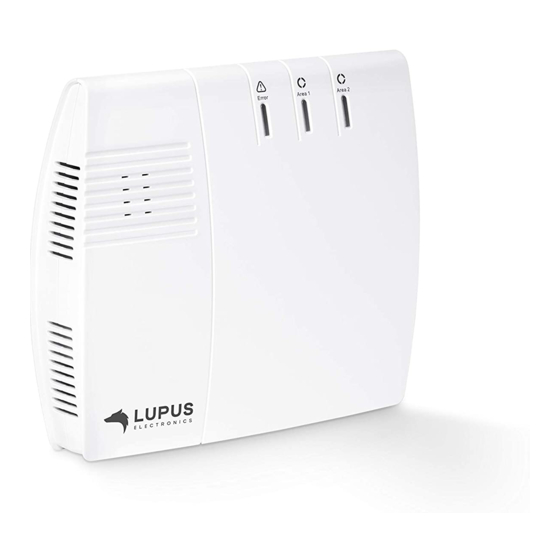
Page 24: Description Of The Leds
Description of the LEDs The LUPUS XT alarm panel has three different control LEDs, which inform you about the alarm panel’s status. XT1 Plus XT2 (Plus) - Page 25 1. Error LED Red = system error (list via “System” “Status” “Panel”) Off = system in correct state 2. Area 1 LED Red = Area 1 in armed mode (Arm) Green = Area 1 in Home mode (Home 1, Home 2, Home 3) ...
- Page 26 mode or Range test mode Off = Area 2 is disarmed, the system memory does not contain any alarm Please note: The LEDs of the XT2 (not Plus) area 1 LED flashes green and area 2 LED red during learn or range test mode.
-
Page 27: Access To The Web Interface Of The Lupusec-Xt Alarm Panel
Access to the web interface of the LUPUSEC-XT alarm panel The alarm panel is controlled via a browser-based user interface, which is structured like a website. On this website, you can control all system functions of the alarm panel, add and edit sensors, arm or disarm the alarm panel, check for open windows or doors, and view pictures from your LUPUSNET HD network cameras and recorders (if installed and connected). - Page 28 Please Note: To gain access to the alarm panel, it must be within the same logical network (e.g. 192.168.100.X) as the accessing device (PC/notebook). If this is not the case, please check your network connection. More information can be found in the chapter “Settings” “Network”. ...
- Page 29 The login window opens: Enter the following default access data upon the initial access: User name: admin Password: admin1234 The installation wizard The installation wizard guides you through the initial set-up of the alarm panel. a) Choose a language b) For reasons of security, you will need to change the password. It is not possible to use the alarm panel with the standard password! Make sure to remember the new password and be aware of major and minor letters.
- Page 30 Important The password needs to be at least 8 characters long (ASCII Code 33-126). A weak password is not accepted (it needs to be at least medium). o Blanks are not allowed! The username may consist of major and minor letters and numbers. o The users “expert”...
- Page 31 can find more information in the chapter “remote access via the internet”. f) Now you can choose between a dark and a light theme for the user interface. The default option is the dark theme and the manual only features the dark theme (the only difference of the themes is the colour –...
- Page 32 Please note: We recommend using Mozilla Firefox for web access to the alarm panel, which is available on the provided CD. You can save the IP address of the alarm panel e.g. in the list of favorites or bookmarks of your browser to access the user interface of the alarm panel in an easier and quicker way.
-
Page 33: User Interface Of The Alarm Panel
User interface of the alarm panel The user interface consists of 5 elements: 1. Main menu The main menu contain the sub-menus to control the alarm panel and consists of: “Home”, “Sensors”, “Smarthome”, “Alarm system”, “Settings”, “System”, “LUPUSEC 24”, and “Logout”. You can change the menu by left clicking on the menu you want to access. - Page 34 2. Quick access menu The quick access menu allows you to display important information about the status of the alarm panel. By pressing on an item, you receive additional information. You can define which items and in which order items are displayed in this menu.
- Page 35 o Mode change This menu allows you to change the mode (disarm, arm, home 1-3) of both areas of the alarm panel. The current mode is highlighted. o Smarthome If you have created a profile in the menu “Smarthome” “Automation”...
- Page 36 o Quick access This menu allows you to define which information is shown in the quick access menu (2). You can change the order of the items via drag&drop (holding the left mouse button and moving the item). o Logout Allows you logout of the user interface of the alarm panel.
-
Page 38: Home Menu
Home menu The home menu features the GRID interface of your alarm panel. Use the LUPUS GRID to personalize the user interface of your XT alarm panel in your browser. You define which indication and information, which functions, and which switches and buttons you want to display. - Page 39 2. Alarm mode app Section 2 shows altogether four alarm mode symbols. Click to set the alarm panel to arm, disarm, or one of the home modes. The section consists of altogether four alarm mode apps. Each app fulfills its own function and enables the mode set in the app settings.
- Page 40 4. Notification app The notification app displays the important sensor and system messages. You only see a list of the latest events. 5. Sensor list app The Sensor list app displays the installed sensors with their icon and name. The column to the right shows the signal strength of the sensor (“WIFI”...
- Page 41 6. Camera app This app displays the live stream of your cameras or recorders. You need to add your cameras or recorder in the menu “Smarthome” “Cameras” in order to display them in the GRID. You can only add one camera app to the GRID. By pressing on the arrows at the left and right when moving the mouse over the live stream, you can circle through all your cameras.
-
Page 42: Configure Overview Page
Configure overview page The new Grid overview page facilitates the individual representation of information of your smart home alarm panel. There is a specific app for each function and each sensor that can be adjusted dynamically in size and, thus, its extent of information. Large Medium Small... - Page 43 Add Grid To adjust your overview page, please proceed as follows: 1. Open the “Control menu” (right click or ) and click on „Unlock grid“. 2. The maximum space available for apps is highlighted in grey. 3. You can drag&drop (left mouse button) to sort the apps in your unlocked GRID.
- Page 44 detector, light sensor, smoke detector). Status notification This app displays the status of the alarm panel. Notification This app displays all the important sensor and system messages. Sensor list The Sensor list app displays the installed sensors with their icon and name. The column to the right shows the signal strength of the sensor (“WIFI”...
- Page 45 Allows you to change the selected app into another one. 2. Size Allows you to change the size of the app. The available sizes depend on the app you want to change. You can also use the mouse to directly change the size of the app directly in the GRID.
-
Page 46: Sensors
Sensors This menu shows the sensor list including all the connected sensors. The submenu “Add” allows you to integrate new sensors to the alarm panel; “Range” is used to test the signal strength; “Universal remote control” allows you to set-up your “universal IR controller”. Note: All components except wireless relays (item no 12014) and repeaters (item no 12016) are counted as sensors. -
Page 47: List
List The menu “Sensors” “List” offers the “Sensors” in a list, as well as, the “alarm overview” list. Sensor list: In this menu, you can find all sensors that are connected to your alarm panel. You can change the sorting of the sensor list by means of the sort symbol at the top of each column: The list contains all information about the sensors. - Page 48 bar indicates that something is not all right, e.g. the sensor is not working. If the bar flashes, it indicates that, e.g. a door contact was opened or closed. Tampering contact The bar is green as long as the tampering contact of the sensor is closed. As soon as the tampering contact opens (e.g.
- Page 49 Alarm overview The Alarm overview displays you at a glance the behaviour of the added sensors in the respective alarm mode (Arm, Home 1-3, Disarm) of the alarm panel. You can change the configuration by clicking on the setting symbol to enter the “Edit sensor”...
-
Page 50: Edit Sensor
Edit sensor You can assign different properties and actions to most of the sensors. In case of an alarm, the sensor reacts according to the set parameters. Depending on the type of sensor, the following settings are available: ID Shows the sensor-specific ID (not editable). - Page 51 Bypass If a sensor is set to bypass, this sensor will not trigger any alarms (does not apply to tampering alarm), as long as the bypass is active. This option is only available for sensors that can trigger an alarm. Please note: If a sensor displays an error (e.g.
- Page 52 of this setting. 24 HR If this function is active, the set alarm is triggered irrespective of the alarm mode of the alarm panel, when the sensor is activated. Disarm / Arm / Home 1 / Home 2 / Home 3 response Set how the alarm panel reacts if a sensor is triggered in the different alarm modes o No response The alarm panel does not react at all, when the sensor is triggered.
- Page 53 but sends a notification according to your “Alarm system” “Report” settings. o Intruder alarm silent If a sensor with this setting is triggered, the sirens do not sound an alarm, but sends a notification according to your “Alarm system” “Report” settings.
-
Page 54: Add
In the menu “Add,” you can add sensors to the alarm panel. Add sensor Click on “Start” at the bottom of the menu to activate the learn mode (the LEDs or Area 1 and 2 begin to flash green). Then begin the adding process of your sensor. Please note: ... -
Page 55: Range
Add device In this menu, you can add devices to the alarm panel. Devices are wireless repeaters (item no. 12016) and wireless relays (item no 12014). Select area 1 or 2 from the drop-down menu next to “Activate device for”, to define the area to which a device should be added (both areas is not possible). -
Page 56: Universal Remote Control
Universal remote control Via the menu “Sensors” “Universal remote control”, you can operate a connected universal IR controller. The universal IR controller was developed to control infrared- controllable appliances automatically and manually. The universal IR controller can learn IR signals and repeat them. After the IR signals have been learned, you can control the corresponding device them via the LUPUS alarm panel without using the related remote control. - Page 57 Press the button to repeat (send out) the saved signal, e.g. to switch the fan on or off. Five appliances with eight functions (signals) respectively can be programmed for each universal IR controller.
-
Page 58: Smart Home Menu
Smart home menu In the Smart home menu, consists of the sub-menus “Automation”, “Wireless Plugs”, “Cameras”, “Capture”, ”power consumption”, “temperature history”, and “Scenarios”. Automation The Home Automation menu allows the creation of up to 100 automation rules, to assign them to up to ten groups, and have them executed in up to five profiles. In the Automation menu, you can set up automations so that e.g. - Page 59 5. Condition: Shows which condition triggers the rule. Each rule can consist up to ten conditions which can be connected via “and” or “or”. If you connect two or more rules via “and”, all the conditions need to be met in order to trigger the home automation rule.
- Page 60 1. Active: Use the checkbox in front to activate or deactivate the group. 2. Effective execution: Green checkmark: Group is active and will be performed if the condition is met. Red exclamation mark: Group cannot be performed. Refer to “Profiles” for details in this regard.
- Page 61 2. Nr.,: A number is assigned to every profile (the first free number is chosen automatically). You can change the number later on be means of the drop- down menu (1-5). 3. Symbol: You can assign a symbol to every profile to quickly identify the profile. 4.
-
Page 62: Home Automation Settings
Home Automation settings In the following, we explain the various options of the home automation menu in detail. In order to create a home automation, you need to insert the following information: Condition – if the condition is met, the home automation is executed. ... - Page 63 power meter and to execute a home automation if the power consumption of this device is above the set value. Energy below Identical to “energy above”, however, the home automation is executed when the energy consumption is below the set value. ...
-
Page 64: Schedule
in schedule is used to calculate the chance that the automation is triggered in every minute of this timespan. The 100% chance of execution of the automation is divided by the minutes in the schedule. Example If you set the condition “random execution” and schedule “every day” “20:00 – 20:10”. -
Page 65: Action
To use the following schedules sunrise, sunset, and daytime you need to select a city or your longitude and longitude in the menu “Settings” “Date & Time”. Sunrise This option allows you to execute a home automation at sunrise. Furthermore, you can set a time in minutes to execute the automation e.g. - Page 66 The color option is only available for Philips Hue Color products. This option allows you to change the color of your lamp. Be aware, that changing the color is only possible while the lamp is switched on. Hence, your automation required to actions: Firstly, switch the lamp on and, secondly, change the color.
- Page 67 the options available for lamp setup. Dimmer group setup If you defined a group of dimmers in the menu “Smarthome” “Wireless Plugs” “Group settings”, this action allows you to control this group according to the options available for dimmer setup. ...
-
Page 68: Examples
Examples Please note: Home automation rules are a very powerful tool to control the devices in your home. However, due to the multitude of possible uses, we cannot offer an example for every possible automation. This chapter aims to give you a brief overview how automations work and how they have to be setup. - Page 69 Example 2 – time control Aim: How to switch on a lawn sprinkler that is connected to a wireless plug in area 1 zone 2 for two hours every evening. Settings: Create a new rule Select “Condition” “Schedule”. ...
- Page 70 Create a second rule. Select “Condition” “Schedule”. Select “Schedule” “Sunset” “+10 minutes”. Select “Action” Shutter setup” “Area 1 Zone 11” “Close”. Click on the to the right of the rule. Example 4 –...
- Page 71 The “Action URL” allows you to send out URL commands via your network. By using the “Action URL” and CGI commands, you can control all kinds of devices (not limited to devices by Lupus Electronics). Please note: In order to use the “Action URL” function, it is necessary to have a sound knowledge of coding.
- Page 72 Settings: Create a new rule Select “Condition” “Mode” “Area 1” “arm.” Select “Schedule” “Always Select “Action” “Action Url” enter the following command into the blank below (without quotation marks): „http://Test:Test@192.168.1.200:80/SetMail.cgi?Mail_Enable=1“ ...
- Page 73 Settings: The settings are identical to the settings in example 5.1. Only the “Action URL” command is different After arming the alarm panel, the motion detection areas of the camera are activated: If you want to deactivate the motion detection upon disarming the alarm panel, you need to create another home automation rule and use “condition”...
- Page 74 Settings The settings are identical to the settings in example 5.1. Only the “Action URL” command is different After arming the alarm panel, the motion detection areas of the camera are activated: If you want to deactivate the motion detection upon disarming the alarm panel, you need to create another home automation rule and use “condition”...
- Page 75 Examples of schedules: The trigger for a home automation are the condition and the schedule. If the condition and the schedule are met, the home automation is executed. Depending upon if you have defined a point in time or a period in your schedule, the home automation is executed under different circumstances.
-
Page 76: Wireless Plugs
Wireless plugs Shows a list of all integrated wireless power supply devices, relays, dimmers, and Smarthome lights (PSS devices). Wireless plugs list The devices are listed with area, zone, type, name, and status. Funktions / Colour circle (only Philips Hue colour Smarthome lights) Clicking on the colour circle opens the colour selection that allows you to change the colour of your Philips Hue Smarthome lights. - Page 77 Percentage drop-down menu o Allows you to adjust the brightness of your dimmer. o Allows you to open / close your shutters to the selected degree (100% = open / 0% = closed) Time drop-down menu o When the PSS device switched off, you can select from the drop-down menu, for how long the selected PSS device is to be switched on.
- Page 78 Schedule The schedule menu allows you to define when a PSS device is switched on and when it is switched off by means of a weekly schedule or a rhythmic interval. Power supply switches / group Select the device or group for which you want to define a schedule or rhythmic interval.
- Page 79 Groups In the group settings, you can summarize wireless power supply devices and relays in a maximum of eight groups and manually activate or deactivate them, activate them for a specific period or activate/deactivate them in an automated manner. Dropdown menu: When the PSS group switched off, you can select from the drop-down menu, for how long the selected PSS device is to be switched on.
- Page 80 Please note: You cannot create groups consisting of different types of devices, since they could have different functions. A device can be assigned to various groups. The following groups can be created: o Switch groups: Remote controlled mains sockets, in wall relays. o Light groups: Smarthome lights with colour selection e.g.
-
Page 81: Cameras
Cameras In this menu you can connect up to eight live stream (XT1 Plus only four) of your LUPUS IP cameras, as well as, most LUPUS recorder (8xx+, 8xxD1, 8xxHD, 8xxHD V2 series, NVRs). As of firmware 2.20 an IP finder is available in the alarm panel. 1. - Page 82 Examples: Integration of a LE 200 camera In order to display the live stream of your LE 200, you should update the firmware of the camera to version 2.21.1.129_p1 (or later). The latest firmware can be downloaded in the download section of the LE 200 on www.lupus-electronics.de. Make sure to set the compression to MJPEG in the menu “Video”...
- Page 83 Integration of an older 800 + / 800 D1 video recorder The URL consists of the following elements: DVR address: 192.168.0.155 Port: 10001 Username: test Password: test Camera image: /cgi-bin/net_jpeg.cgi? Channel: 3 Example URL: http://test:test@192.168.0.155:10001/cgi-bin/net_jpeg.cgi?ch=2 Please note: You need to subtract 1 from channel number. Channel 3 become ch=2 in the URL command.
-
Page 84: Capture
Capture Image events This menu displays all recent recordings of your PIR cameras, sorted by zone, picture, and date. Click on a recorded picture to zoom in. A maximum of six PIR network cameras can be added to the alarm panel. PIR cameras This menu displays the added PIR network cameras. -
Page 85: Power Consumption
Power consumption The table on the bottom of the screen shows the current, the average, and the extrapolated power consumption of the added devices with electric meter (e.g. remote controlled mains socket or in-wall relay # 12051). You can select if you want to display the power consumption of the last hour, day, week, or month. -
Page 86: Temperature History
Temperature history The table at the bottom of the screen shows the current temperature of your temperature sensors, as well as, the average, minimum, and maximum temperature. You can select if you want to display the temperature graph for the last hour, day, week, or month. -
Page 87: Scenarios
Scenarios Up to 16 scenarios with up to five automation rules each can be set up. A scenario is a combination of the individual commands. When you perform a scenario, all rules of this scenario are performed at once. allows you to create a new scenario. -
Page 88: Alarm System
Alarm system Comprises the sub-menus settings, siren settings, report, and PIN codes. Settings Use this menu to define the general settings, area, and alarm settings. General settings Report power interruption Specify the time after which the alarm panel reports a power failure (Contact ID, e- mail, SMS, etc.). - Page 89 Restart device to schedule Use this function to schedule the regular restart of the alarm panel. After enabling this option, it takes 24 hours until it is performed for the first time. Hence, it is not possible to test a “restart in 5 minutes” with this option. Please note: After a restart, the alarm panel has no information about the sensors and all sensors (even open door contacts) are listed with “N/A”.
- Page 90 Internal sensors (only XT3) In your sensor list, you find two “door contacts (intern)” and one “power switch (intern)”. More information about these can be found in the chapter “The internal I/O terminal of the XT3”. In case you are not using these connectors, you can deactivate them via in this menu. Afterwards, they are also removed from the sensor list.
- Page 91 Area settings Settings for area Specify for which area the following settings shall apply. Main settings Name You can name the selected area. The name will be included in e-mails/text messages from the alarm panel. Final Door Activate this option if you want to arm the alarm panel when the last open door contact is closed during the exit delay.
- Page 92 Tamper alarm o Arm (default): In case of a tampering alarm, the sirens sound an alarm only in arm mode. They remain silent in all other modes (Disarm, Home 1-3). o Always: In case of a tampering alarm, the sirens always sound an alarm – irrespective of the alarm mode of the alarm panel.
- Page 93 Date and time General Date Enter the current date (YYYY/MM/DD). Time Allows you to manually enter the current time (HH:MM). Click on “Synchronize” to use the current time of your computer. Time zone Enter your current time zone. ...
- Page 94 location). Please note: o You can display the sunrise and sunset times in the quick access menu. Internet timeserver Automatically synchronize with internet time server If you enable this option, the time of the alarm panel synchronizes regularly with the specified internet timeserver (if available).
-
Page 95: Siren Settings
Siren settings Sirens This menu consists of two parts. The upper part allows you to transmit settings to all connected indoor and outdoor sirens. The lower part lists your connected sirens and allows you to enter the sensor edit menu of the sirens. ... - Page 96 alarm panel! In this case, you should wear ear protection and disconnect the siren as quick as possible from its power supply. Confirmation signal on/off (with Arm / Disarm) With this function active, the siren will sound one signal tone when arming and two signal tones when disarming the alarm panel.
- Page 97 Activate siren strobe Specify whether the LEDs of the siren are to flash after the acoustic alarm has ended until the system is disarmed again. Confirmation strobe Specify, whether the siren is to flash for confirmation, when the alarm mode of the alarm panel changes (Arm/ Home / Disarm).
- Page 98 Personal threat Panic and emergency alarm Medical emergency Gas, CO, medical alarm External siren(s) If additional sirens are connected to the alarm panel, you can specify, in which cases they shall sound an alarm. If several external sirens are connected, you cannot configure them individually –...
- Page 99 Setting for area Set for which of the two areas you want to adjust the settings. Doorbell Set the volume of the doorbell. During the entry delay time (Arm mode) Set the volume for the entry delay while the alarm panel is in arm mode. ...
-
Page 100: Report
Report Notifications In this menu, you can define whether the alarm panel shall notify you in case of alarms, status changes or all events. You can select between the options to send text messages via GSM or via the internet, to be notified via a phone call (via SIM card), and via e-mail. To reduce the risk of failures, you can set tup to 25 receivers in this menu To use the different notification methods, you need either, a SIM card (with deactivated PIN code), an internet connection and a account with one of the supported SMS clients,... - Page 101 you in case of status events, alarm events, or all events. Additionally, you can specify these events in the drop-down menu to the right. These additional filters are active as soon as you have selected at least one alarm or event. Then, you will only be notified about the alarms or events you have manually selected.
- Page 102 o Server The IP address of the security firm server o Port The assigned port of the security firm server o Sample URL: ip://123456@94.214.112.83:2280/SIA Level Specify when to transmit a report: o All events: Each status change and alarm will be transmitted. o Alarm events: Only alarms will be transmitted.
- Page 103 The most important event codes: ALARM REPORTS Code Alarm Cause Medical alarm Detector with medical alarm feature Emergency alarm Medical emergency controller, panic button Fire alarm Detector with fire alarm feature Smoke alarm Smoke detector Heat alarm Heat detector Hold-up alarm Panic button on remote control Panic alarm Hold-up code on keypad...
- Page 104 Example of contact ID syntax: The account 1234 reports a perimeter alarm in zone 15 of area 1: <1234 18 1131 01 015 8> 1234 = Account at the security firm = Identification of a report via Contact ID 1131 = The first digit (here: 1) stands for “New event” and is followed by the event-code (131) which stands for a perimeter alarm = Area number = Zone number...
-
Page 105: Pin Codes
PIN codes In this menu, you can define PIN codes and special codes for area 1 and area 2. You can only enter PIN codes in a connected (Outdoor) Keypad. You can use a single (Outdoor) Keypad to control both areas of the alarm panel. Depening on the PIN code you use, the corresponsing area reacts. - Page 106 If you set a date, the PIN code is valid starting from this point in time. If you leave the field blank, the PIN code is immediately valid. Expiry date You can set a date in the form 22/09/2016 08:00. After this set date/time, the PIN code is no longer valid.
-
Page 107: Settings
Settings The settings menu comprises the sub-menus network, e-mail account, SMS account, SIM card, and device integration. Network In this menu, you can set-up the IP address of the alarm panel. We recommend the default setting “Receive IP address automatically (DCHP)”, if your network includes a router. - Page 108 on “Static IP address assignment.” The advantage of a static IP address is that the IP address of your XT is fixed and will never change. Depending on your router, a static IP address might be required to guarantee a constantly working remote access (you can find more information about port forwarding in the FAQ "General"...
- Page 109 name servers. As an alternative, you can also define a server manually (e.g. google: 8.8.8.8). DNS 2: A domain name server is required for the name resolution of internet addresses, hence for the communication with the internet. In most networks, the IP address of the router can be used.
-
Page 110: E-Mail Account
E-mail account In order to send e-mails it is necessary to have an e-mail account with an e-mail provider. In this menu, you need to enter the specific information of your e-mail provider. You can find these information on the website of your e-mail provider or by means of the common search engines. - Page 111 Example for a gmail account: SMTP settings Server: smtp.gmail.com SMTP port User name Your Gmail e-mail address Password Your Gmail e-mail password Sender Your Gmail e-mail address enable You need to enable the option “Permit access to your account by less secure apps” in your gmail account to allow the mail delivery by the alarm system.
-
Page 112: Sms Account
SMS account In case of an alarm, the alarm panel is able to send a text messages to your mobile phone. (see chapter “Alarm system” “Report”). In this chapter the gateway configuration for “SMS via Internet” is explained. GATEWAY settings ... - Page 113 TEST SMS This test applies exclusively to sending text messages via an internet provider. Receiver: Enter the mobile number to which you want to send a test text message (via the internet). If you use an international number, please type in 00 before the country code (e.g.
-
Page 114: Sim Card
SIM card Settings (“SMS via GSM”) The alarm panel can notify you in case of an alarm or about status changes (see chapter “Report”) via a SMS or a phone call. This menu is about the configuration of the GSM module to use “SMS via GSM”... - Page 115 Status message Indicates the provider of the inserted SIM card and the signal strength. Reporting the status of SIM card This option must be set to for the SMS delivery via SIM card, as it is otherwise impossible. ...
- Page 116 Use this command to switch wireless power supply devices and in-wall relays on or off. Switch First value (1) Area number 1 (PSS) PSS:test,1234,1,2,0 Second value (2) PSS zone number 2 device Third value (0) 0 Switch-off command on/off 1 Switch-on command 2 Switch-over command...
-
Page 117: Device Integration
Device integration Alexa Service The Alexa skills are currently only available in German and require Alexa to be connected to the German Amazon.de store. If you Alexa is connected to e.g. the American, British, France, etc. Amazon store, you cannot use these skills. If you have Alexa connected to the German Amazon.de store and are able to use the German Alexa skills (commands + answers only in German), please contact us if you require an English manual. - Page 118 NUKI This menu allows you to connect your alarm panel to a NUKI door lock. NUKI locks are door locks that use Bluetooth to connect to a Nuki Bridge. The bridge is connected via WLAN to your network and can be controlled via the Nuki app, and, after the integration, with your alarm panel.
- Page 119 Go to the menu “Sensors” “Add” “Add Sensors” and click on “start”. Add the Nuki door lock (Door Lock) to the alarm panel Please note: As long as the information in the Nuki menu are correct and the Nuki bridge is connected to your network, the door lock is displayed in your sensor list.
-
Page 120: System Menu
System menu This menu contains the system settings and allows you to check the system status, logs, login information, perform firmware updates, backups, and a reset to default. Status Panel At the top of the menu, you see the battery status of the alarm panel, the status of the tampering contact of the alarm panel (only XT1 Plus and XT3), if there are any radio interferences, the power supply of the alarm panel, the GSM signal strength, and the signal strength of the alarm panel. - Page 121 Every new system error triggers a regular audio alarm. You can disable each of these warnings with “Ignore system malfunction” Please note If the list contains a system error that was not ignored, this will be indicated upon arming or activation of the home mode.
-
Page 122: Logs
Logs The logs menu you find the various logs of your alarm panel sorted in the categories: System messages, notifications, system events, reported events, and sensor messages. Below each log table, you can select how many entries you want to display. ... -
Page 123: Password
Reported events This menu displays messages of the alarm panel including the corresponding contact ID codes (see chapter “Contact ID syntax”). Sensor messages This menu displays all sensor messages concerning temperature, humidity, and power consumption. Password In this menu, you can change the login information of the three accounts of the alarm panel. - Page 124 Active: In order to use the “expert” or “user” account, you first need to activate account New user: Assign a new name for the account or continue using the current name. Old password: Enter the admin password or the current password of the account you want to change.
-
Page 125: Firmware
Firmware In this menu, you can update the firmware and sensor firmware of the alarm panel, as well as, save a backup file / load a backup file to the alarm panel, and export a system log file. Firmware You can see immediately, which firmware is installed (installed version) and if a newer version is available (latest firmware version). - Page 126 Configuration System log file Click on download to save a .tar file that includes all logs of the alarm panel. Configuration backup If you enter the admin password and click on download, you can save a .bin file that includes all settings of the alarm panel (sensors + configurations) ...
- Page 127 Sensor firmware In case it is necessary to update the sensor firmware, it can be done in this menu. Sensor software This menu shows you the software version of your sensors. It is not possible to install an update.
-
Page 128: Factory Reset
Factory reset Use this menu to reset all the alarm panel’s settings to default (software reset). Installed firmware: Shows you the currently installed firmware Keep network setting: If you enable this option, the network settings are not reset. ... -
Page 129: Logout
o XT2 (Plus) o XT3 Reconnect the mains adapter to the alarm panel. After approx. 40-50 seconds, all three LEDs flash and the alarm panel emits a loud continuous notification signal for 2-3 seconds. Now you can release the learn button. ... -
Page 130: Remote Access Via The Internet
Remote access via the internet The LUPUS alarm panel allows you to retrieve and control the status of the entire system via the internet, an iPhone/iPad, or Android mobile phone. Even the pictures form your LUPUS cameras or recorders can be displayed. To be able to access the alarm panel via the internet, check the following items beforehand: 1. -
Page 131: Port Forwarding
Port forwarding In most of the cases, you open the login page of your router by entering your standard gateway address (gateway to the internet) in the web browser. You get this gateway IP address in Windows Clients by clicking on Start and then entering “CMD”... -
Page 132: Access Via The Lupus App (For Android + Ios)
Access via the LUPUS app (for Android + iOS) Download the free Android or iOS app from Google Play Store or the App Store (iPhone/iPad). Most of the settings can be done with the app. However, network settings cannot be changed. The following screen is shown when you first start the app: You can select between the methods “assistant”... - Page 133 Using the assistant: 1. Follow the instructions of the app and click on “continue”. 2. Select which alarm panel you have.
- Page 134 3. The assistant shows you detailed information how your alarm panel needs to be connected. 4. All devices of the selected type are displayed.
- Page 135 5. The app connects to the alarm panel. Enter your login information. If you have not changed the default password (admin1234) yet, you now need to change it. Important The password should consist of at least 6 characters, numbers, and special characters.
- Page 136 6. When you access the device for the first time, you are asked to assign an IP address (we recommend using DHCP). The installation wizard allows you to create a hostname for internet access. Enter a name and click on “create hostname” to check if this hostname is still available. In case the name is not available anymore, please enter a different one.
- Page 137 7. This page displays an explanation how a port forwarding is set-up. The button “how to I create a port forwarding” opens a list containing various routers to display detailed information. Even more information can be found on our homepage in the FAQ section “Remote access via the internet”.
- Page 138 9. After having finished all steps, there are now two profiles in your app. In some cases (e.g. when using a Fritz!Box), a single profile is sufficient to have local and world-wide access. Other routes (without a NAT-loopback function) require separate profiles (one for local access, one for remote access).
- Page 139 Using expert mode If you are already experienced in creating new profiles and know all login information, you do not need to use the assistant every time. Device Chose the type of device you want to connect from the drop-down menu. ...
-
Page 140: Profile List
Profile list When you start the app / after creating your first profile, you see the following screen: Tap to log in with this profile Create new or additional profile Press on the name of the created profile to log into your alarm panel. Press on the gear symbol to edit the settings of the profile (e.g. -
Page 141: Usage Of The Alarm Panel App
Usage of the alarm panel app The default interface features the following 10 items. 1. Shows you yet unread system messages of the alarm panel. If you have already read the messages, you find them in the menu “Main menu” “Logs” 2. - Page 142 between different home automation profiles (if you have already created one or more profiles via “Smarthome” “Automation”). 6. The dashboard. You can add sensors, switches, cameras, etc. to the dashboard. After they have been added, you can change their size and move them around on the dashboard.
- Page 143 Most of these sub menus are identical to the their corresponding menus in the browser interface. Hence, we only explain the menus that are only available in the app or which are different from the browser interface. The menu Notifications allows you to set-up the push notifications of the alarm panel.
- Page 144 The menu App opens an overview of all your sensors and devices that can be displayed on the dashboard. The green checkmark indicates that they are already displayed on the dashboard. App menu allows you to change which options are displayed at the bottom of the app (slots 7-9).
- Page 145 Unlock allows you to move the items on your dashboard via drag and drop. Use the locked lock icon to lock the dashboard again. By clicking on the name of your profile, a profile lists opens and you can connect to a different profile of the app.
-
Page 146: Alarm Test
Alarm test After installing the alarm panel, you can simulate an alarm in order to test the function of the individual sensors and if the alarm panel reacts as you want it to. We advice using a door contact for this test. ... -
Page 147: Description Of Sensors And Controls
Description of sensors and controls The LUPUS alarm panel supports various sensors, detectors, and devices. All of them are connected wirelessly to the alarm panel. An alternating encryption ensures a safe two-way communication between the alarm panel and the sensors. The following describes a variety of accessories to be connected to the LUPUSEC-XT2 (Plus) alarm panel. -
Page 148: Overview Of Sensors Compatibility
Overview of sensors compatibility The following table provides an overview of which sensor is compatible with which alarm panel (XT1, XT1 Plus, XT2, XT2 Plus, or XT3). XT1 Plus, XT2 Plus, Item No. Product and XT3 Connection 12052 12/24V relay ZigBee S 1 channel relay 12126... - Page 149 Keypad 12001 Keypad V2 12106 RF / RC Light switch 12046 ZigBee S Light switch V2 12072 ZigBee S 12065 Light sensor ZigBee S Curtain motion detector 12110 Magnetic lock 12035 Mechanical lock 12036 Medical emergency controller 12009 Mini indoor siren 12032 EOL ZigBee Mini indoor siren V2...
- Page 150 Key: EOL = no longer available. Compatible with the indicated devices. X = Compatible and available Blank = Not compatible Green = Range can be enhanced by wireless repeater V2 (#12122) Orange = Range can be enhanced by remote controlled mains adapter with Zigbee Repeater (#12050), 1+2 channel relay (#12126 + #12127), mini indoor siren V2 (#12032 –...
-
Page 151: The Internal I/O Terminal Of The Xt3
The internal I/O terminal of the XT3 Your XT3 features two potential free (dry contacts) inputs and one output. The inputs allow you, just as the sensor input, to connect wired devices of other manufacturer (e.g. existing door contacts, fingerprint, motion detectors, access control), to your alarm panel. - Page 152 o GND: This is the input for the second wire of your potential fee alarm sensor. The other wire is connected to IN1 or IN2. Thus, if you are using both sensor inputs, two wires are connected to GND. If the potential free alarm sensor is triggered, and the circuit is closed, the status of the sensor changes accordingly.
-
Page 153: Integration Of Lamps Of Other Manufacturers
Integration of lamps of other manufacturers You can connect Smarthome lamps of other manufacturers to your alarm panel. We tested lamps of Philips Hue, Osram Lightify, Innr, IKEA; and Paulmann with our alarm panels. Requirements: XT1 Plus, XT2 Plus, or XT3 (firmware 0.0.2.18 or above). ... - Page 154 Installation: 1. In case the lamp is already connected to a gateway or remote control, please reset the lamp. 2. Open the menu “Sensors” “Add” -> “Add Sensors” und click on “start”. 3. Switch the lamp on. 4. The alarm panel lists the lamp as dimmer and can be added with .
- Page 155 Clicking on the middle of the app switches the lamp on and off. Holding the toggle on the circle allows you to dim the light. Additionally, lamps with colour selection have a colour control circle at the upper left. Please note: ...
-
Page 156: 12 / 24 V Wireless Relay
12 / 24 V wireless relay Attention: This product is not compatible with the XT1 or XT2 without “Upgrade dongle to XT2 Plus.” ATTENTION: The installation may only be performed by a person who is trained, certified, and has a profound knowledge about electronic devices and electrical engineering Product description: The 12 / 24 V wireless relay can switch a potential-free contact similar to the wireless... -
Page 157: Connecting The 12 / 24 V Wireless Relay And Putting It Into Operation
Wiring diagram: We advise a cable diameter of 16–26 AWG or Ø 1.31-0.129 mm². Connect the 12/24V relay according to following wiring diagram: Please note: 12V/24V always requires a 12V DC or 24V DC mains adapter. The relay does not output the voltage to the connected device (via 6+7 / 7+8). The connected device requires a separate power supply. - Page 158 Please Note: “Sensors” “List” “Status” shows the status of the relay (on 7 off). The 12 / 24 V wireless relay can be activated or deactivated manually via the web interface of the alarm panel (“Smarthome” “Wireless plugs” or “Home” “Radio switch list”).
-
Page 159: Channel Relay
1 channel relay Attention: This product is not compatible with the XT1 or XT2 without “Upgrade dongle to XT2 Plus.” ATTENTION: The installation may only be performed by a person who is trained, certified, and has a profound knowledge about electronic devices and electrical engineering Product description: The single channel relay allows you to wirelessly (ZigBee S) control a connected power... -
Page 160: Connecting The Single Channel Relay And Putting It Into Operation
Wiring diagram: Connect the single channel relay according to the following diagram: You can use an external switch (see figure) to switch the single channel relay on or off. It is not possible to use a push-button switch instead of a switch! ... - Page 161 Please note: If the signal strength at the place of installation is below 4, we advise to use a ZigBee repeater, since it is normal that the signal strength may fluctuate for 2-3 points, thus, a signal loss is possible. Please note: ...
-
Page 162: Channel Relay
1 channel relay Attention: This product is not compatible with the XT1 or XT2 without “Upgrade dongle to XT2 Plus.” ATTENTION: The installation may only be performed by a person who is trained, certified, and has a profound knowledge about electronic devices and electrical engineering Product description: The double channel relay allows you to control a connected power circuit (24 - 230V... -
Page 163: Connecting The Double Channel Relay And Putting It Into Operation
Wiring diagram: Connect the double channel relay according to the following diagram: You can use an external switch (see figure) to switch the double channel relay on or off. It is not possible to use a push-button switch instead of a switch! ... - Page 164 Please note (signal strength): If the signal strength at the place of installation is below 4, we advise to use a ZigBee repeater, since it is normal that the signal strength may fluctuate for 2-3 points, thus, a signal loss is possible. Please note: ...
-
Page 165: 360° Pir Motion Detector
360° PIR motion detector Product description: The 360° PIR motion detector alarms you dependably about any movements in your rooms. You simply need to install the 360° PIR motion detector at the location that you want to secure. The 360° PIR motion detector works by means of passive infrared monitoring in a 360°... -
Page 166: Connecting The 360° Pir Motion Detector And Putting It Into Operation
Connecting the 360° PIR motion detector and putting it into operation 1. Insert the included battery into the battery compartment of the 360° PIR motion detector. 2. The 360° PIR motion detector will now enter a boot process. This takes approx. 30 seconds and the LED will flash during this time. - Page 167 We advice you to install the 360° PIR motion detector in the following way: o On the ceiling with as few obstacles as possible in the detection range. o Near the entrance / door of a room to register if someone enters or exits that room.
-
Page 168: Co Detector
CO detector Product description: The CO detector of the LUPUSEC-XT is a sensor that detects the highly toxic carbon monoxide gas and reports reliably and promptly to the alarm panel whenever the natural level is exceeded, which triggers the alarm accordingly. The CO detector is battery- operated and communicates wirelessly with the alarm panel. - Page 169 Range test: 1. Open the alarm panel menu “Sensors” “Range” and press “Start”. 2. Press the Learn button of the CO detector. 3. The sensor and the signal strength should be indicated. The higher the indicated number the better the reception (1-9). Please note: If the signal strength at the place of installation is below 4, we advice to use a wireless repeater, since it is normal that the signal strength may fluctuate for 2-3 points, thus,...
-
Page 170: Curtain Motion Detector
Curtain motion detector Product description: The curtain motion detector detects movements via passive infrared monitoring (changes of the infrared wavelength radiation) in a distance of up to 10 meters (10.9 yards). The narrow detection angle of 10° is similar to a photo-electric guard. Hence, the curtain motion detector is perfect to secure passages. -
Page 171: Connecting The Curtain Motion Detector And Putting It Into Operation
range test, and to start the test mode. 6. Jumper (JP2 and JP3) By default, the two jumper (JP2 and JP3) are not set. Open position JP2 (supervision): Active – please do not change this setting JP3 (sensitivity): Set to “normal” level Closed position ... - Page 172 Installation The angle of detection of the curtain motion detector is 10° and 110° (vertically or horizontally - depending on the alignment of the device). The sensor detects movements only if the 10° angle is crossed (see arrows in the examples below). The curtain motion detector is designed to be installed on a wall or ceiling.
- Page 173 After you have decided the place of installation, install the curtain motion detector on a flat and even surface. The back of the curtain motion detector has two markings for drilling. Drill through these markings and use them as a gauge.
-
Page 174: Door Contact
Door contact Product description: The LUPUS door contact is an integral part of your alarm system and is used to secure your windows and doors. The contact consists of two parts: one is fixed at your window or door frame, the other one is fixed at the wing of the door or window sash. Thus, the window/ door contact immediately registers if a window or door is opened or closed. -
Page 175: Connecting The Door Contact And Putting It Into Operation
LED indicator: Under normal circumstances, the LED of the door contact will be off. It only flashes in the following cases: If the door contact is removed or turned in a different position (the tampering contact is opened). If the battery is low and the sensor is opened. ... - Page 176 Installation: The sketch above shows the how the sensor and the magnet can be placed. Other installation positions are possible. We advise to install the sensor at the door or window frame and the magnet on the door leaf or window casement. ...
-
Page 177: Door Contact V2
Door contact V2 Product description: The LUPUS door contact V2 is an integral part of your alarm system and is used to secure your windows and doors. The contact consists of two parts: one is fixed at your window or door frame, the other one is fixed at the wing of the door or window sash. Thus, the window/ door contact V2 immediately registers if a window or door is opened or closed. -
Page 178: Connecting The Door Contact V2 And Putting It Into Operation
1. LED / Learn button 2. Magnetic contact markings 3. Switch for the status monitoring 4. Tampering contact 5. Battery compartment 6. Mounting hook 7. Mounting holes 8. Notch for opening the sensor 9. Tampering contact opening 10. Opening for the battery breaker 11. - Page 179 Please note: If the signal strength at the place of installation is below 4, we advise to use a wireless repeater, since it is normal that the signal strength may fluctuate for 2-3 points, thus, a signal loss is possible. Installation: ...
- Page 180 Be aware that the magnet needs to be within 20 (0.78 inches) of the marking (2) in order to be displayed as closed. You can check the status of the sensor in the menu “Sensors” “List” of the alarm panel. Note: ...
-
Page 181: Dual-Way Motion Detector
Dual-way motion detector Product description: The dual-way motion detector prevents false alarms due to a double motion detection method – PIR and microwave detection. An alarm is only triggered if both methods detect a motion. The PIR/microwave motion detector consists of a front and a back. The mainboard to make various settings/adjustments is located on the front. -
Page 182: Connecting The Pir / Microwave Motion Detector And Putting It Into Operation
Jumper On Jumper Off The jumper bridges the two The jumper is removed or is on pins. one pin only. The supervisor mode is deactivated with Jumper 2 set to ON. The supervisor mode is activated with Jumper 2 set to OFF (default setting). 8. - Page 183 4. Open the configuration menu of the alarm panel and then the menu “Sensors” “Add”. Press “Start”. 5. Press the Learn button of the detector once. The menu should list the PIR/microwave motion detector after a short while. Press to complete the connection process.
- Page 184 Note: The LEDs (on the front) and the single mounting hook (on the back) must point upwards for the installation. First, install the respective mount to the intended place of installation. Then, fix the PIR/microwave motion detector on the respective mount. The mounting hooks need to lock in place on the back of the motion detector.
-
Page 185: Electric Meter
Electric meter Warning: This product is not compatible with the XT1 or XT2 without “Upgrade dongle to XT2 Plus.” Product description: The electric meter can easily be installed in or next to your fuse box in order to monitor the power consumption in your home. The electric meter uses the IR interface of your fuse box to receive this information. -
Page 186: Connecting The Electric Meter And Putting It Into Operation
for more than 10 seconds, the electric meter is reset and a new connection request is send out to the alarm panel. 6. IR sensor Connect the cable of the IR sensor with the IR sensor input (4). Connecting the electric meter and putting it into operation 1. - Page 187 main electric meter. The IR interface needs to remain accessible (double-sided tape and washers are included). 2. The IR sensor of the electric meter is equipped with a magnet. Place the sensor on the washer in a way that the sensor can connect with the IR interface of your main electric meter.
- Page 188 Set-up of the electric meter In the menu “Sensors” “List” , you can change the name, area, and zone of the electric meter. Furthermore, you can set the impulse factor in order to match the measurement correctly. In the example image above, you can see that our main electric meter offers a value with 10000 imp/kWh.
-
Page 189: Emergency Button
Emergency button Product description: The emergency button is used to trigger an emergency alarm in order to notify others and request help. 9. LED indicator The LED lights up briefly when a signal is transmitted. 10. Learn- / emergency button ... -
Page 190: Connecting The Emergency Button And Putting It Into Operation
Connecting the emergency button and putting it into operation 6. Remove the battery breaker from the emergency button to energise the devise. 7. Open the main menu of the alarm panel. 8. Open the menu “Sensors” “Add”. 9. Click “Start”. 10. - Page 191 Loops Hooks Remove the protective cover on the back of the hooks side of the Velcro and glue this pad to the intended place of installation. Remove the protective cover on the back of the loops side of the Velcro and glue this pad to the back of the emergency button.
-
Page 192: Glass Breaking Sensor
Glass breaking sensor Product description: The glass breaking sensor detects the sound of breaking window glass and notifies the alarm panel. In order to avoid false alarms, two inputs are required to trigger an alarm: First, the sensor registers the breaking of glass and, then, the pieces of glass falling to the ground. - Page 193 connection process. Close the housing of the glass breaking sensor again. Range test: 1. Open the alarm panel menu “Sensors” “Range” and press “Start”. 2. Press the Learn button of the glass breaking sensor. 3. The sensor and the signal strength should be indicated. The higher the indicated number the better the reception (1-9).
- Page 194 Do not install the glass breaking sensor in the following locations In rooms with soundproof coating or curtains (anechoic rooms). In corners of a room. In full glass air locks, very loud kitchens, garages, tool rooms, staircases, bathrooms or other small and loud rooms.
-
Page 195: Glass Breaking Sensor V2
Glass breaking sensor V2 Product description: The glass breaking sensor V2 detects the sound of breaking window glass and notifies the alarm panel. Sensor data: Dimensions (without mount) 7.5 x .7.5 x 2.38 cm (2.95 x 2.95 x 0.93 inches) Weight: approx. -
Page 196: Connecting The Glass Breaking Sensor V2 And Putting It Into Operation
Connecting the glass breaking sensor V2 and putting it into operation Open the housing of the glass breaking sensor V2. Insert the battery. Open the main menu of the alarm panel. Open the menu “Sensors” “Add”. Click “Start”. Press the learn button of the glass breaking sensor V2 briefly. The alarm panel will confirm the successful addition with a brief signal tone and display the glass breaking sensor in the menu “Sensors”... - Page 197 Please note: You can mount the glass breaking sensor V2 on a wall or on a ceiling. The glass breaking sensor V2 triggers an alarm if it detects a hit on the window and, then, the breaking of glass. ...
-
Page 198: Heat Detector
Heat detector Product description: The heat detector is equipped with two sensors. One measures the temperature and the other measures how fast the temperature changes. If the temperature rises faster than 8.3°C per minute or rises above 57.3°C (135.14F), an alarm will be triggered (95dB). The heat detector is perfect for the kitchen, since, due to steam, normal smoke detectors are prone to trigger false alarms. - Page 199 and press “Start”. 5. Press the Learn button of the heat detector. The menu should list the heat detector after a short while. Press to complete the connection process Range test: 1. Open the alarm panel menu “Sensors” “Range” and press “Start.” 2.
-
Page 200: Indoor Siren
Indoor siren Product description: 1. Mounting holes 2. Battery compartment 3. Learn button 4. Tampering contact (inside) 5. Power switch 6. Speaker 7. Tampering contact (outside) Includes: 4 x screws +dowels 4 x 1.5V D alkaline batteries Connecting the indoor siren and putting it into operation 1. - Page 201 Range test: 13. Open the alarm panel menu “Sensors” “Range” and press “Start.” 14. Press the learn button. 15. The sensor and the signal strength should be indicated. The higher the indicated number the better the reception (1-9). Please note: If the signal strength at the place of installation is below 4, we advise to use a wireless repeater, since it is normal that the signal strength may fluctuate for 2-3 points, thus, a signal loss is possible.
- Page 202 The wireless indoor siren requires 4 D-cell alkaline batteries. The average battery life is 2 years (depending on the usage. Reset Delete the siren form the alarm panel (“Sensors” “List”). Switch the power switch to off. Remove any residual current by pressing and releasing the lean button and the tampering contact 2-3 times.
- Page 203 disconnect the ones you do not want to change from their power supply. It is not possible to display the current setting of a siren. Tamper on/off Deactivates the tampering contact of all currently connected “external” sirens for one hour (useful e.g.
- Page 204 All areas To use the siren for both areas, please follow these instructions: o Activate the option “all areas”. o The siren emits a confirmation sound. o Test if the siren now follows the settings of both areas (e.g. emits the entry/exit delay) o The same procedure is necessary if you want to change the area of the siren.
- Page 205 Signalton Arm/Home 1 Beep* Disarm 2 Beeps* Arm (law battery) 5 Beeps Disarm (low battery) 5 Beeps Arm (tampering) 5 Beeps Disarm ( tampering ) 2 Beeps* Pre-alarm 3 sec Beep Tampering alarm ContinuousBeeps Entry / exit delay Beeps every second until the delay ends...
-
Page 206: Keypad
Keypad Product description: 1. Power LED 2. Status LED 3. Error LED 4. Arm 5. Home 6. System status 7. Disarm 8. Pound key # 9. Star key * Installation mode = Installation PIN + * 10. Emergency alarm: 7 + 9 (simultaneously) 11. -
Page 207: Connecting The Keypad And Putting It Into Operation
o Alarm panel does not respond o Incorrect PIN code o Attempted to switch to home mode while the alarm panel is in arm mode o Forced activation of arm mode while alarm panel or sensors report an error o If the status check never works correctly, the keypad was not added fast enough to the alarm panel. - Page 208 keypad emits a signal sound and the power LED is switched off. Now you can arm and disarm the alarm panel by means of the keypad. Range test: 1. Enter the installation mode of the keypad (default: 0000 + *) 2.
- Page 209 Please note: To use the dual key functions, you need to press the buttons for at least three seconds. To use the dual key functions, you may only press the two corresponding buttons at once. Description Input Additional functions ...
- Page 210 In the menu “Alarm system” “Settings” “General settings” a “PIN code protection” can be activated. After five incorrect PIN code inputs, the keypad is locked for 15 minutes. The keypad V2 uses a rolling code encryption. Attention: Change the standard PIN code (1234) as well as the installation PIN code (0000) of the keypad to ensure that no one else can control your alarm panel! You can change...
-
Page 211: Light Sensor
Light sensor Attention: This product is not compatible with the XT1 or XT2 without “Upgrade dongle to XT2 Plus.” Product description: Use the light sensor to determine the brightness of the room in which it is installed. This allows you to set up automation rules, e.g. that the light is turned on automatically at night. The latest version (sold since the end of 2017) also features a temperature and humidity measurement. -
Page 212: Connecting The Light Sensor And Putting It Into Operation
5. Control button Hold the control button pressed for ten seconds to reset the light sensor and to send a connection request to the alarm panel. Pressing the button briefly transmits a supervisor signal and the current lux value to the alarm panel. - Page 213 Operation: The sensor checks the brightness every minute and transmits it to the alarm panel every 30 minutes. If the currently measure lux value is ten percent above or below than the last value, this is reported immediately to the alarm panel and shown as lux level in the sensor list.
-
Page 214: Light Switch V2
Light switch V2 CAUTION: Only certified electricians or persons instructed in electrical engineering with knowledge and understanding of electric current and the inherent risks are allowed to execute the installation. Attention: This product is not compatible with the XT1 or XT2 without “Upgrade dongle to XT2 Plus.”... -
Page 215: Installation Of Light Switch V2
2. Circuit 1 Use the top part (+) to switch your lamp on and the lower part (-) to switch your lamp off. Briefly pressing one of the buttons activates or deactivates the power supply for the circuit 1 (7). ... - Page 216 Note: Please observe that the listed colours are only examples. If you cannot identify the corresponding cables or you have doubts, please consult an electrician. To use the light switch V2, you require a line and a neutral conductor. ...
- Page 217 Range test: 16. Open the alarm panel menu “Sensors” “Range” and press “Start.” 17. Press the learn button. 18. The sensor and the signal strength should be indicated. The higher the indicated number the better the reception (1-9). Please note: If the signal strength at the place of installation is below 4, we advise to use a ZigBee repeater, since it is normal that the signal strength may fluctuate for 2-3 points, thus, a signal loss is possible.
- Page 218 Power supply The light switch V2 is powered by the connected power circuit of your home. Supervision Every 30 minutes, the light switch V2 transmits a supervision signal to the alarm panel. If you press a button of the light switch, a supervision signal is transmitted as well. Control via the alarm panel The light switch V2 can be controlled the menu “Smarthome”...
-
Page 219: Lockswitch Contact
Lockswitch contact Product description: The lockswitch contact is used in combination with a sensor input. If the contact is opened, an alarm or an entry delay can be triggered depending on the settings. Additionally, the alarm panel can be armed or disarmed by unlocking/locking (not available for XT1). -
Page 220: Connecting The Lockswitch Contact And Putting It Into Operation
Connecting the lockswitch contact and putting it into operation: 1. Insert the supplied battery. 2. Set the DIP switch 1 to ON. 3. Connect the contacts of the lockswitch contact to terminal 6. 4. Switch SW5 to “ON”. This is necessary in order to allow the sensor input to transmit a regular status signal to the alarm panel. - Page 221 you can automatically arm/ disarm the alarm panel. The alarm panel is automatically armed or disarmed, depending on whether the contact is closed or open. o Normally closed The sensor is normally closed and arms the alarm panel when opened. o Normally open The sensor is normally open and arms the alarm panel when closed.
-
Page 222: Magnetic Lock
Magnetic lock Product description: A magnetic lock in your door ensures that you can only open the door if you have previously disarmed your alarm panel. Thus, false alarms are securely prevented. You can overcome the magnetic lock with an effort of 60 kg. The magnetic lock is combined with the wireless relay and, thus, can be connected to the alarm panel (wireless relay is included). -
Page 223: Installing The Magnetic Lock To The Door And Putting It Into Operation
Installing the magnetic lock to the door and putting it into operation Installation to door frame: 1. Bracket for magnetic lock 2. 2.5 cm screw 3. Magnetic lock 4. Allen screw (0.5 cm) 5. Metal plate 6. Metal tube (horizontal fixing) 7. -
Page 224: Mechanical Lock
Mechanical lock Product description: The mechanical lock is used to lock doors mechanically with a bolt, thus, you can only open the door when the alarm panel is disarmed. This prevents false alarms. The mechanical lock this is part of a mechanism to fulfil inevitability. The mechanical lock locks only after the door was closed. -
Page 225: Installing The Mechanical Lock To The Doorframe And Putting It Into Operation
Installing the mechanical lock to the doorframe and putting it into operation For reasons of safety, the bolt of the mechanical lock can only be activated if the magnetic plate is located opposite of the lock. Thus, it is necessary to install the magnetic plate parallel to the mechanical lock. - Page 226 Make sure that the red and black wires exit the mount through the opening opposite of the bolt. Push the bracket cover back and tightly fix it again by means of the two Phillips screws. Install the smaller mount for the magnetic place, similar to the lager mount of the lock, to the door.
-
Page 227: Medical Emergency Controller
Medical emergency controller Product description: Dimensions (LxWxH): 38.6 x 25 x 10.9 cm (15.19 x 9.84 x 4.29 inches) Weight: Sensor: 8 gram (0.01 lbs), Strap: 18 gram (0.03 lbs) Place of installation: Mobile: Wristband or necklace Operating temperature: -10 °C to +50 °C (14F to 122F) Humidity: Maximum 85% (non-condensing) Water resistance:... - Page 228 Battery: The medical emergency controller requires a CR2032 3 V lithium button cell. The average battery life is approx. four years (if trigger twice a day). It is not possible to exchange the battery of the medical emergency controller, the complete controller needs to be replaced. Activate battery status indicator: If required, you can activate the battery status indicator (supervision function).
-
Page 229: Outdoor Keypad
Outdoor keypad Front view Rear view Rear view (open housing) Housing bracket Product description: 1. Power LED 2. Status LED 3. Error LED 4. Tag reader 5. F1 – F4 buttons 6. Arm button Home button Disarm button Status button 7. - Page 230 The Power LED lights up blue and the keypad beeps twice. If the keypad returns into standby mode before you completed your entries, the entries will be rejected. If the outdoor keypad is supplied by a mains adapter, you can operate it directly without prior activation.
-
Page 231: Connecting The Outdoor Keypad With Tag Reader And Putting It Into Operation
If you use the outdoor keypad V2 with the mains adapter, you can control it directly without needing to touch the sensitivity line. Battery: o The outdoor keypad can be operated with the included 12V mains adapter and/or two 1.5 V lithium batteries. o If the mains adapter is connected and batteries inserted, the outdoor keypad is supplied by the mains adapter. - Page 232 3. Enter * + 7 subsequently in the keypad. The keypad should be displayed in the alarm panel. 4. Add the keypad to the alarm panel. 5. To exit the installation mode, press the Disarm button twice. The keypad emits an audio signal and the Power LED goes off shortly after.
- Page 233 red status LED lights up 2. Disarm: User PIN (default 1234) + Disarm button. Two audio signals are emitted and the blue status LED lights up. 3. Activate Home mode: User PIN (default 1234) + Home and then 1, 2, or 3 to activate the required home mode.
- Page 234 armed during this time, the relay will close again. Please note: The relay of the outdoor keypad reacts upon mode change of the alarm panel (via browser, keypad, remote control, smartphone, etc.) as long as the outdoor keypad is powered by the mains adapter. If the outdoor keypad is only powered by the batteries, the relay will only react when the mode changed is performed by the outdoor keypad.
- Page 235 2. To delete all learned tags linked to a PIN code, enter the PIN code and then press the Status key. A long beep is audible. To delete a single tag from the outdoor keypad, press the status key in the tag configuration mode and hold the tag in front of the tag reader.
- Page 236 Enter the installation mode of the keypad (default 0000 + *). The power LED lights up orange. To activate the dual key function, you need to enter the following commands for the corresponding functions: * + 2 activate dual key 1+3 (panic alarm) * + 3 activate dual key 4+6 (fire alarm) * + 4 activate dual key 7+9 (medical alarm) * + 5 Deactivate all dual key functions...
- Page 237 * + 6 Change the installer PIN code: * + 6 Enter the previous PIN code (default 0000). Press the Status key . A long audio signal is audible. Enter a new 4-digit PIN code. Press the hash key #. ...
- Page 238 You can configure the alarm panel so that the alarm mode is always changed irrespective of system errors: “Alarm system” “Settings” “Area settings” “Arming with failure” change “Confirm” to “Force”. If a system error is indicated (status LED flashes blue), you can usually ignore it by repeating the entry for arming or home mode within ten seconds.
-
Page 239: Outdoor Siren V2
Outdoor siren V2 The outdoor siren V2 features an IP56 protection class and, in case of alarms, alerts you by activating the siren and a stroboscope. The outdoor siren V2 can also alert in case of tampering, low battery, or radio communication interferences. Product description: 1. -
Page 240: Connecting The Outdoor Siren V2 And Putting It Into Operation
Connecting the outdoor siren V2 and putting it into operation 1. Open the outdoor siren V2 by unscrewing the screws on the bottom. 2. Unscrew both screws of the LED cover and remove the cover. 3. Supply the outdoor siren with power (see power supply descriptions above). 4. - Page 241 Supervision: The outdoor siren V2 sends a supervisor signal every 30 to 50 minutes. If the signal is not received by the alarm panel, the web interface shows the status “Out of order.” Alarm simulation 1. You can test the siren’s function by simulating an alarm or triggering the tampering contact.
- Page 242 This menu allows you to configure “external” sirens that are added to the alarm panel. It is not possible to configure the internal siren of the alarm panel in this menu. All settings in this menu are only transmitted and saved on the siren(s). The web interface does not display the current setting of the sirens.
- Page 243 o Activate the option all areas. o LED 2 will light up and a brief confirmation signal sounds. o Press the learn button again. LED1&3 light up. o Change another option of the siren (e.g. change area 1 to area 2). o LED 2 will light up and a brief confirmation signal sounds.
- Page 244 Exit strobe Specify, whether the LEDs of the siren are to flash for confirmation during the delay when leaving. Entry strobe Specify, whether the LEDs of the siren are to flash for confirmation during the delay when entering. Please note: o If you disable the “input”...
-
Page 245: Panic Button
Panic button Product description: 1. Panic button If this button is pressed for at least 3 seconds, the alarm panel will trigger an alarm regardless of which mode the alarm panel is in (Arm / Disarm / Home). If this button is pressed for at least 10 seconds, the panic alarm stops. -
Page 246: Pir Motion Detector V2
PIR motion detector V2 Product description: The PIR motion detector V2 alarms you dependably about any movements in your rooms. You simply need to install the PIR motion detector V2 at the location that you want to secure. The PIR motion detector V2 works by means of passive infrared monitoring. Sensor data: Dimensions (without mount) 6.4 x 4.2 x 9.4 cm (2.5 x 1.6 x 3.7 inches) (WxDxH) -
Page 247: Connecting The Pir Motion Detector V2 And Putting It Into Operation
2. PIR sensor 3. Battery breaker (delivery status) 4. Tampering contact 5. Corner mount 6. Battery compartment LED: Usually, the LED indicator does not flash. Please be aware of the following exceptions: If the battery runs low, the LED will flash for two seconds after a movement was detected. - Page 248 since it is normal that the signal strength may fluctuate for 2-3 points, thus, a signal loss is possible. Installation: There are five holes at the back of the PIR motion detector (three slots, two small holes) – these are used to install the corner mount ...
- Page 249 The PIR motion detector V2 will detect motions in a range up to 12 meters (13 yards) if it is installed in a height of 2 meters (6.5 feet). To ensure the optimal function of the PIR motion detector V2, make sure that the PIR motion detector V2 is installed in a height of 1.8 –...
-
Page 250: Pir Network Camera V3
PIR network camera V3 Product description Attention: This product is not compatible with the XT1 or the XT2 (without the “Upgrade Dongle to XT2 Plus”). Product description: The PIR network camera is a motion detector with an integrated mini snapshot camera. When the RAS (Infrared Reflection Absorption Spectroscopy) sensor detects a motion, images will taken immediately and send to your alarm panel. -
Page 251: Connecting The Pir Network Camera V3 Und Putting It Into Operation
Connecting the PIR network camera V3 und putting it into operation 1. Open the housing of the PIR network camera V3. 2. Insert the battery. The PIR network camera V3 can only be connected during the first three minutes after the battery is inserted. 3. - Page 252 Attention: Do not install the PIR network camera within the detection range of another detector (e.g. motion detector with light in front of the entrance door). Do not expose the PIR network camera to direct sunlight. The PIR motion detector registers movements in the temperature field. Thus, it can also be triggered by the movements of air currents.
- Page 253 By clicking on in the menu “Sensors” “List” or “Smarthome” “Capture” you can request a single image. The PIR network camera is not compatible with the wireless repeater. The PIR network camera cannot be saved in the configuration file. ...
-
Page 254: Radiator Valve Thermostat V2
Radiator valve thermostat V2 Attention: This product is not compatible with the “XT1” or the XT2 without an additional “upgrade dongle to XT2 Plus!” Before you install the radiator valve thermostat, clean and lubricate the heater valve. Tight or rusty valves may damage the radiator valve thermostat beyond repair. - Page 255 In “Manual mode”, you can configure the radiator valve thermostat only by means of the temperature control (4) or the manual configuration of the thermostat control of the XT alarm panel, however, not via the schedule settings! In „Automatic mode“, you can configure the radiator valve thermostat via the schedule settings of the XT alarm panel (menu “Sensors”...
-
Page 256: Installation Of Radiator Valve Thermostat V2
5. Battery compartment The radiator valve thermostat requires two 1.5 V AA alkaline batteries. Other functions: Anti-frost: If the radiator valve thermostat detects the risk of frost, the valve opens automatically and causes the temperature to rise. Anti-calcification: To prevent calcification, the valve opens and closes once a week Saturday night at 11 p.m. - Page 257 Range test: 1. Open the alarm panel menu “Sensors” “Range” and press “Start”. 2. Press the learn button. 3. The sensor and the signal strength should be indicated. The higher the indicated number the better the reception (1-9). Please note: If the signal strength at the place of installation is below 4, we advise to use a ZigBee repeater, since it is normal that the signal strength may fluctuate for 2-3 points, thus, a signal loss is possible.
- Page 258 thermostat may vary from the room temperature. In the thermostat control menu, can therefore define a temperature offset between -2.5 °C and +2.5 °C. Example: If the radiator valve thermostat is installed under a windowsill where the temperature is 2° warmer than in the rest of the room (20° at the windowsill, 18° in the room), then, the temperature offset should be set to -2°.
- Page 259 If the setpoint temperature is inceased, the valve is opened further in order to reach the setpoint temperature. In the menu “Smarthome” “Temp. history”, the temperature of the last hour, day, week, or month is displayed. In the menu “Smarthome” “Automation”, you can set rules for an automatic control of the radiator valve thermostat.
-
Page 260: Relay With Power Meter V2
Relay with power meter V2 CAUTION: Only certified electricians or persons instructed in electrical engineering with knowledge and understanding of electric current and the inherent risks are allowed to execute the installation. Attention: This product is not compatible with the “XT1” or the XT2 without an additional “upgrade dongle to XT2 Plus!”... -
Page 261: Connecting Relay With Power Meter For Xt2 Plus And Putting It Into Operation
1. LED indicator On: relay on Off: relay off Flashes twice: signal transmission 2. Learn button Pressing the button briefly activates or deactivates the relay. Press the Learn button for ten seconds or longer to reset the relay and send a learn signal to the control unit. - Page 262 alarm panel. 6. Keep the Learn button (1) pressed for approx. ten seconds; the LED lights up briefly. Release the Learn button. The relay transmits the connection request and the LED flashes twice. 7. As soon as the alarm panel has received the connection request, the sensor list shows the sensor.
-
Page 263: Remote Control V2
Remote control V2 The remote control allows you switch between the different modes of the alarm panel (arm, disarm, home), as well as, to trigger a panic alarm. Product description: 1. Arm-button By pressing this button for approx. three seconds, you arm the alarm panel. This will be signalled by a long tone of the alarm panel. -
Page 264: Connecting The Remote Control V2 And Putting It Into Operation
Connecting the remote control V2 and putting it into operation 1. Use a coin to open the battery compartment. 2. Install the battery with the negative pole facing down (the flat, positive pole faces up). 3. Close the battery compartment again. 4. -
Page 265: Remote Controlled Mains Socket With Power Meter And Zigbee Repeater
Remote controlled mains socket with power meter and ZigBee repeater Attention: This product is not compatible with the “XT1” or the XT2 without an additional “upgrade dongle to XT2 Plus!” Product description: With an integrated wireless socket, you can supply a connected end device with power remotely (via web access/smartphone) or by manually pressing the LED button. -
Page 266: Connecting The Wireless Socket And Putting It Into Operation
1. LED indicator / learn button: The LED indicator is at the same time the Learn button. LED on: power on LED off: power off LED flashes fast twice: successfully added to the alarm panel The red LED flashes every twenty minutes, if the PSS is not connected to the alarm panel anymore. - Page 267 with ZigBee repeater can be connected in series. Ten other ZigBee devices can be repeated per socket with ZigBee repeater. The wireless mains socket does not need to be switched on in order to repeat the signals of other devices. Note: ...
-
Page 268: Scenario Switch V2
Scenario switch V2 Attention: This product is not compatible with the XT1 or XT2 without “Upgrade dongle to XT2 Plus!” Product description: The scenario switch V2 features four buttons. Each button allows you to trigger a scenario or home automation rule. Sensor data: Place of installation: Only indoors... -
Page 269: Connecting The Scenario Switch V2 And Putting It Into Operation
Flashes twice: The scenario switch V2 was added successfully to the alarm panel. 6. Installation notches Connecting the scenario switch V2 and putting it into operation 1. Insert the batteries into the battery compartment of the scenario switch. 2. You can add the scenario switch V2 to the alarm panel only within the first three minutes after having connected the scenario switch to the its power supply! 3. - Page 270 Operation First, define the automation rules for the respective scenario via the menu “Smarthome” “Scenarios.” For further information, please refer to the chapter “Scenarios.” Then, go to the menu “Sensors” “List” (of the scenario switch V2) and define which scenario should be performed when the scenario switch is used.
-
Page 271: Sensor Input
Sensor input Product description: The sensor input is a device with two potential-free switch contacts. The sensor input is connected wirelessly to the alarm panel. If the contacts are closed, an alarm is triggered. Therefore, it can be used for already available window/ door contacts in a wired system or additional sensors by third-party providers (access control, fingerprint, light barrier, door bolt contact etc.). -
Page 272: Connecting The Sensor Input And Putting It Into Operation
DIP switch functions: Use the switches 1-4 to assign a function to the sensor input and, thus, define whether it is listed in the alarm panel as door contact, motion detector, smoke detector, or panic button. Never activate (ON) more than one of the four switches simultaneously. Afterwards, add the sensor to the alarm panel. - Page 273 3. The sensor and the signal strength should be indicated. The higher the indicated number the better the reception (1-9). Please note: If the signal strength at the place of installation is below 4, we advise to use a repeater, since it is normal that the signal strength may fluctuate for 2-3 points, thus, a signal loss is possible.
-
Page 274: Sensor Input (9 Fold)
Sensor input (9 fold) Attention: This product is not compatible with the XT1! CAUTION: Only certified electricians or persons instructed in electrical engineering with knowledge and understanding of electric current and the inherent risks are allowed to execute the installation. Product description: The sensor input (9 fold) connects wirelessly to the alarm panel and features nine dry contact (potential free) inputs for wired sensors. - Page 275 7. Power terminal +12V / GND Input 12V AUX/GND Output You can use the output to supply other devices with 12V. The power output features 12V (100mA). 8. Backup battery connector 9. Drill holes Power supply and battery: Connect a 12V DC mains adapter to the power terminal. Connect the positive conductor to (+12V) and negative cable to (GND).
-
Page 276: Calibrating The Sensor Input (9 Fold)
Calibrating the sensor input (9 fold) 1. During calibration, all sensors connected to the wireless input are registered. 2. When you add the sensor input to the alarm panel, every connected contact counts as an individual sensor / zone in the alarm panel. Hence, the alarm panels displays the status of every connected sensor individually. - Page 277 3. The alarm panel shows you the sensor and the corresponding signal strength. The higher the indicated number the better the reception (1-9). Please note: The alarm panel regularly checks the signal strength of the sensor and shows you the latest signal strength in the menu “Sensor” “List”. ...
-
Page 278: Shutter Relay V2
Shutter relay V2 CAUTION: Only certified electricians or persons instructed in electrical engineering with knowledge and understanding of electric current and the inherent risks are allowed to execute the installation. Attention: This product is not compatible with the “XT1” or the XT2 without an additional “upgrade dongle to XT2 Plus!”... - Page 279 1. LED indicator Flashes once: relay was reset Flashes twice: relay was added to the alarm panel Flashes once every 20 minutes: Connection to the alarm panel lost 2. Learn button Briefly press it to transmit a status signal to the alarm panel ...
- Page 280 Wiring diagram: Connect the neutral conductor (N) of the shutter relay V2 to the neutral conductor (N) of the power supply. Connect the phase (L) of the shutter relay to the phase (L) of the power supply. Connect O1 of the shutter relay to the up cable of the shutter motor (L).
-
Page 281: Connecting The Shutter Relay V2 And Putting It Into Operation
Connect the other wires according to the same principle with the Wago terminals. Depending on the used devices (motor, push buttons, etc.) additional Wago terminals might be necessary. If you do not use a push button, we advise you to use Wago terminals on the wires of S1 and S2 in order to prevent a short circuit. - Page 282 Options in the edit sensor menu: In order to use the percentage control of the shutter relay, you need to enter the exact time your shutter need to completely open and close. It is normal that your shutter takes a little longer to open than to close. Enter the measured time into the fields “Time to open”...
- Page 283 Note: Only connect one shutter motor to one shutter relay. You can save dynamic or time programs in the Automation menu. The shutter relay is not compatible with the wireless repeater and cannot be saved in the backup file. ...
-
Page 284: Small Indoor Siren V2
Small indoor siren V2 Attention: This product is not compatible with the XT1 or XT2 without “Upgrade dongle to XT2 Plus.” Product description: The indoor siren can be used with every customary socket. It sounds an alarm signal at 95 dB in case of alarm. Additionally, the siren functions as a ZigBee S repeater (since manufacturing date 2019) and automatically enhances the range of other Zigbee devices. -
Page 285: Connecting The Small Indoor Siren And Putting It Into Operation
Connecting the small indoor siren and putting it into operation 1. Plug the indoor siren into a socket at the intended place of installation. 2. Only within the first three minutes after having connected it to the power grid, can you add the mini indoor siren to the alarm panel! 3. - Page 286 Advanced settings: You can access this menu via “Sensors” “List” The option “all areas” allows you to assign the small indoor siren V2 to both areas. Small indoor sirens V2 (since 2018) allow you to select the alarm volume, confirmation beep, the entry/exit delay volume, and the doorbell signal.
-
Page 287: Smoke Detector V2
Smoke detector V2 Product description: The smoke detector V2 works according to optical principles. In a measurement chamber, the concentration of smoke particles is measured. If the concentration exceeds a set limit, the smoke detector will sound an alarm of 85dB (measured from a distance of 1 meter / 3.2 feet). - Page 288 Only install 3x AA batteries. The average battery life is approx. 2.5 years. When the batteries run low, the smoke detector will notify you acoustically and optically. When you change the batteries, make sure to press the learn button a couple of times before you insert the new batteries –...
-
Page 289: Connecting The Smoke Detector V2 And Putting It Into Operation
measurement chamber and trigger an alarm. In areas for which the smoke detector V2 is not suited (e.g. warmer than 45°C/113F or colder than -10°C/14F) such as not isolated attics, cold store, or boiler rooms. In areas that are hardly accessible or have very high ceilings (for testing and disabling the alarm). - Page 290 inserted since the smoke detector V2 adapts to the conditions at the place of installation (e.g. amount of dust in the air). After the warm-up phase (six minutes) the calibration phase starts. The calibration phase takes between two and sixteen minutes and every 100 seconds, the smoke detector V2 emits a brief signal.
- Page 291 situations. Please note: The smoke detector V2 will always sound an alarm if the smoke concentration is too high – irrespective of its connection to or status of the alarm panel. It is not possible to connect smoke detectors V2 with each other. Only the smoke detector that detected the smoke will sound an alarm.
-
Page 292: Status Display
Status display Please note: This product is not compatible with the XT1 or XT2 without “Upgrade dongle to XT2 Plus.” Description: The status display shows you if your alarm panel is armed or disarmed. Sensor-data: Place of installation: Indoor and outdoor Protection class: IPX4 Working environment:... -
Page 293: Connecting The Status Display And Putting It Into Operation
ZigBee status: Flashes red once: Status display is reset. Flashes red twice: The status display was successfully added to the alarm panel Flashes every twenty minutes: The status display has lost contact to the alarm panel. 2. Casing screw 3. - Page 294 Installation: The status display can be installed in two ways. Either by using the included adhesive tape, or by using the included screws. Please do not use adhesive tape on rough surfaces, dirty surfaces or on paint that peels of easily. Attachment points for the screws Installation with screws: 1.
-
Page 295: Tag Reader V2
Tag Reader V2 Product description: 1. Power LED (green) 2. Status LED (red) 3. Arm button 4. Disarm button 5. Batteries 6. Function switches 7. Tampering contact 8. Tag (watertight) LED indicators: Both LEDs are off in the stand-by mode. ... -
Page 296: Connecting The Tag Reader V2 And Putting It Into Operation
Function switches: If the tag reader’s housing is open, you will see the function switch block with five switches. These switches are all set to OFF by default. Description Switch no. Position Learn / add mode SW 1 Normal Operation (default) Factory setting SW 2 Normal operation (default) - Page 297 three times and two signals sound, indicating the successful integration of a tag in the tag reader. 4. If you want to add several tags, hold them one after the other (at intervals of 5 seconds) in front of the tag reader or restart the entire process. 5.
-
Page 298: Temperature Sensor V2
Temperature sensor V2 Attention: This product is not compatible with the XT1 or XT2 without “Upgrade dongle to XT2 Plus.” The LUPUSEC temperature sensors measure the temperature at the place of installation and transmits any change directly to the alarm panel every ten minutes. - Page 299 The temperature sensor is not compatible with the wireless repeater and cannot be saved in the backup file. The signal of the temperature sensor V2 can be enhanced by a ZigBee repeater. The operating temperature is between -10 °C and +50 °C (14F to 122F).
-
Page 300: Temperature Sensor With Display V2
Temperature sensor with display V2 Attention: This product is not compatible with the XT1 or XT2 without “Upgrade dongle to XT2 Plus.” The temperature sensor with display V2 measures the temperature and humidity at the place of installation, displays the information, and transmits any change of temperature directly to the alarm panel every ten minutes. - Page 301 the housing. 2. Insert the three supplied AAA batteries in the sensor. 3. You can add the temperature sensor with display to the alarm panel only within the first three minutes after having connected the temperature sensor to its power supply! 4.
-
Page 302: Temperature Sensor With External Probe
Temperature sensor with external probe Attention: This product is not compatible with the XT1 or XT2 without “Upgrade dongle to XT2 Plus!” The LUPUS temperature sensors measure the temperature at its place of installation and transmits any change directly to the alarm panel every ten minutes. The external probe allows you to measure the outside temperature or the temperature of water. -
Page 303: Connecting The Temperature Sensor With External Probe And Putting It Into Operation
Connecting the temperature sensor with external probe and putting it into operation 1. Open the housing and insert the batteries into the battery compartment. 2. You can add the temperature sensor with external probe to the alarm panel only within the first three minutes after having inserted the battery! 3. -
Page 304: Top-Hat Rail Relay
Top-hat rail relay Attention: This product is not compatible with the XT1 or XT2 without “Upgrade dongle to XT2 Plus.” Product description: Top-hat rail relays can be installed in control cabinets in only a few steps and allow you to control connected end devices remotely (web interface/ smartphone) or by hand. You can also set up automation rules, e.g. -
Page 305: Connecting The Top-Hat Rail Relay And Putting It Into Operation
1. Current input Neutral conductor = N / blue. Line conductor = L / brown 2. Current output Neutral conductor = N / blue. Line conductor = L / brown 3. External antenna port To increase the transmission power, you can optionally connect the external antenna so that is located outside of the control cabinet. - Page 306 Please note: If the signal strength at the place of installation is below 4, we advice to use a ZigBee repeater, since it is normal that the signal strength may fluctuate for 2-3 points, thus, a signal loss is possible. Note: ...
-
Page 307: Universal Ir Controller
Universal IR controller Attention: This product is not compatible with the XT1 or XT2 without “Upgrade dongle to XT2 Plus.” The universal IR controller was designed to control infrared-controllable appliances automatically as well as manually. It learns and repeats signals of remote controls. After the respective signals were learned, you can control the appliances with your LUPUS system without the related remote controls. -
Page 308: Connecting The Universal Ir Controller And Putting It Into Operation
Connecting the universal IR controller and putting it into operation 1. Open the housing of the universal IR controller by loosening the screw at the bottom. 2. Insert the provided batteries in the battery compartment. 3. Open the menu “Sensors” “Add” and press “Start” in the web interface of the alarm panel. - Page 309 Select appliance type The universal IR remote control can learn up to eight IR signals respectively of five different appliances. At first, select the appliance with DIP switch block 1, referring to the following table. Switch 1 Switch 2 Switch 3 Switch 4 Switch 5...
- Page 310 Exit the IR learn mode Press the IR button once to exit the learn mode. Then, set all DIP switches to “OFF”. Test signals: After the signals were learned, test the proper function as described in the following. 1. Do not activate the learn mode. Set the DIP switches to the signal to test as described above.
-
Page 311: Installation
Installation The universal IR controller is intended for wall mounting. Either you screw the back of the controller directly to the wall or by means of a pivotable mount. For this purpose, install at first the mount to the wall and then attach the universal IR controller to the mount. Please observe the following pages below, before you choose the place of installation. -
Page 312: Ir Led Selection And Operation
IR LED selection and operation Via the menu “Smarthome” “Universal remote control”, you can assign names to the IR devices and signals, as well as, trigger the IR signals. As long as you do not have a universal remote control connected to your alarm panel, this menu is empty. -
Page 313: Upgrade Dongle To Xt2 Plus
Upgrade dongle to XT2 Plus Product description: The upgrade dongle serves to upgrade an XT2 alarm panel (item no. 12025) to support the new home automation modules working with the ZigBee S protocol. SSL encryption similar to the new XT2 Plus alarm panel is impossible due to lacking CPU resources. The dongle only compatible with the XT2 alarm panel. -
Page 314: Vibration Sensor
Vibration sensor The vibration sensor dependably registers shocks and vibrations. This sensor is ideal for the protection of windows, doors, or various other objects and alarms you immediately at the first attempt of an intrusion. Data: Dimensions 44mm (1.73 inches) Ø, 16mm (0.62 inches) height Weight: approx. -
Page 315: Connecting The Vibration Sensor And Putting It Into Operation
Connecting the vibration sensor and putting it into operation 1. Remove the battery breaker. 2. Open the main menu of the alarm panel. 3. Open the menu “Sensors” “Add”. 4. Press “Start”. 5. Press the learn button (1) of the vibration sensor for a couple of seconds. The red LED (2) will flash. - Page 316 Sensitivity settings: You can set the sensitivity of the Shock sensor in the menu “Sensors” “List” “edit.” Sensor sensitivity: You can choose between two types and three different sensitivity settings: low, medium, high. Type: If you choose “shock”, the vibration sensor only requires a single shock or a single push in order to trigger an alarm.
-
Page 317: Water Sensor
Water sensor Product description: The water sensor allows you to be alarmed about imminent flooding and to react in time. Sensor data: Dimensions (without mount): 7 x 3 x 12cm (4.7 x 2.7 x 1x1 inches) Kable length: 40 cm (15.7 inches) Weight: 160 Gramm (0.35 pounds) IP protection class:... - Page 318 Range test: 1. Open the alarm panel menu “Sensors” “Range” and press “Start”. 2. Press the test button. 3. The sensor and the signal strength should be indicated. The higher the indicated number the better the reception (1-9). Please note: If the signal strength at the place of installation is below 4, we advice to use a repeater, since it is normal that the signal strength may fluctuate for 2-3 points, thus, a signal loss is possible.
-
Page 319: Water Sensor V2
Water sensor V2 Attention: This product is not compatible with the XT1 or XT2 without “Upgrade dongle to XT2 Plus.” Product description: The water sensor allows you to be alarmed about imminent flooding and to react in time. If the probe detects water for more than ten seconds, the water sensor sends an alarm signal to the alarm panel and both emit acoustic alarms. -
Page 320: Connecting The Water Sensor V2 And Putting It Into Operation
Connecting the water sensor V2 and putting it into operation 1. Remove the screw from the housing bottom. 2. Install the supplied batteries. 3. You can add the water sensor V2 to the alarm panel only within the first three minutes after having connected it to its power supply! 4. - Page 321 4. Break open the notches recessed for wall mounting. 5. Use the provided screws to screw the water sensor tightly to the wall. 6. Close the housing again. 7. In order that the cable does not to hang loosely from the wall, use the plastic clips to attach it.
-
Page 322: Wireless Relay
Wireless relay Product description: 1. Control LED 2. Function switches 3. Terminal clamps 4. 9V Jumper 5. Buzzer Includes: 1 x 9V DC mains adapter 2 x screws and dowels 1 x attachment strip 1 x Manual 1 x wireless relay Connecting the wireless relay and putting it into operation 1. - Page 323 7. The alarm panel should recognise the wireless relay and confirm this with a long signal. If not, repeat step 5. 8. Set SW1 of the wireless relay back to OFF. The LED of the wireless relay should flash every second. Please note: ...
-
Page 324: Wireless Repeater V2
Wireless repeater V2 You can connect only a limited number of sensors to the XT alarm panel. If the range of one or more sensors is insufficient, you can increase the range with the wireless repeater V2. The wireless repeater V2 allows you to nearly double the transmission range, because the sensors are sending their signals first to the repeater and then the repeater relays these signals to the alarm panel. -
Page 325: Connecting The Wireless Repeater V2 And Putting It Into Operation
8. Tampering contact on / off The tampering contact presses against the mount that allows you to install the wireless repeater V2 on a wall. As long as the wireless repeater V2 is connected to the mount, the tampering contact is closed. If the wireless repeater V2 is removed from the mount, a tampering alarm is send to the alarm panel. - Page 326 1. The wireless repeater V2 needs to be active (green LED is on). 2. Press the “learn button (sensor)”. The yellow LED lights up. 3. Activate the learn mode of the sensor you want to add. Press the learn button of the sensor as it is explained in the manual of the respective sensor.
- Page 327 If you connect multiple repeaters, the distance between the repeaters should also be at least 10 meters (10.9 yards). All repeaters need to be added to the alarm panel. You need to add a sensor to all repeaters that are used for the transmission of its signal to the alarm panel.
- Page 328 If a sensor is in the range of more than one wireless repeater V2, we advice you to connect the sensor to the repeater which is closer to the alarm panel. In the example above, you would add the sensor to repeater B. ...
- Page 329 Remarks:...
- Page 330 Remarks:...
- Page 331 Remarks:...
- Page 332 Remarks:...
Need help?
Do you have a question about the XT2 and is the answer not in the manual?
Questions and answers