
Related Manuals for Gayk HRE 3000


Summary of Contents for Gayk HRE 3000
- Page 1 Hydraulic Ram Unit HRE 1000 / HRE 3000 / HRE 4000 Translation of the original operating instructions...
- Page 2 Gayk Baumaschinen GmbH Dieselstraße 3 D-63762 Großostheim Telephone: +49-6026 97885-0 Telefax: +49-6026 9788529 E-mail: info@gayk-baumaschinen.de Internet: www.gayk-baumaschinen Publisher's copyright: These operating instructions are intended for installation, operations and maintenance personnel. They may be duplicated, translated or made available to others only with the expressed approval of the publisher. Also,...
-
Page 3: Table Of Contents
Table of contents Table of contents Basic information ......................... 5 Notes on the operating instructions ................ 5 Explanations in the operating instructions .............. 5 Proper use ......................5 Usage conditions ....................6 Guarantee and liability .................... 6 Safety instructions ....................... 7 Standards and guidelines .................. - Page 4 Table of contents Transport ..........................41 General transport instructions ................41 Incoming inspections by the operator ..............41 Assembly and start-up ....................... 43 General assembly instructions ................43 Aligning the machine .................... 43 Operating the machine ....................... 45 7.1.1 General instructions ....................45 7.1.2 Operating procedure .....................
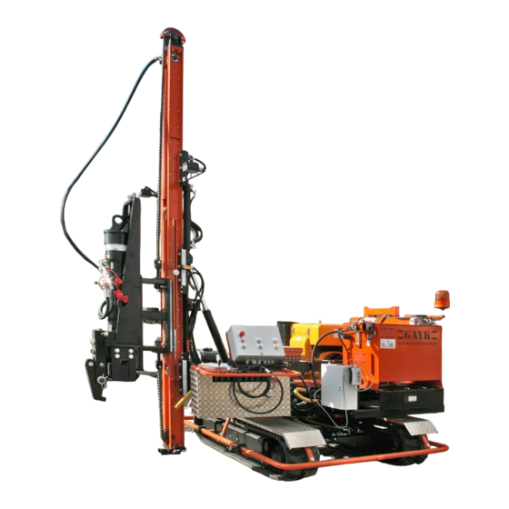
- Page 5 Table of figures Table of figures Fig. 1: Nameplate ........................19 Fig. 2: Main assemblies with optional accessories ..............21 Fig. 3: Chassis ........................22 Fig. 4: Machine in the transport position ................. 22 Fig. 5: Locking and positioning lever ..................23 Fig.
- Page 6 Table of figures Issue 06.2016 Hydraulic Ram Unit HRE...
-
Page 7: Basic Information
Explanations in the operating instructions NOTE Hydraulic ram unit HRE 1000/ HRE 3000/ HRE 4000 is only called a machine in the following chapters of these operating instructions. Proper use The machine may only be operated in its technically proper state and only for its intended purpose, in accordance with these operating instructions. -
Page 8: Usage Conditions
Basic information Usage conditions Before beginning work, check the area to make sure it meets the following criteria: Make sure there are no cables, lines, sewer lines, etc., in the area that could present a hazard. Prepare the work area according to how it is found. If necessary, re-route, disconnect, or secure existing lines. -
Page 9: Safety Instructions
Safety instructions Safety instructions Standards and guidelines The machine is designed according to the current state of the art according to recognised safety rules. The machine was designed according to basic safety requirements, standards and guidelines. All safety information refers to currently applicable ordinances of the European Union (EU). -
Page 10: Explanation Of Labels In The Operating Instructions
Safety instructions Explanation of labels in the operating instructions DANGER Type and source of danger! Immediate danger with high risk of death or serious bodily injuries. Measures to avoid danger. WARNING Type and source of danger! Possible danger with medium risk of death or serious bodily injuries. Measures to avoid danger. -
Page 11: Safety Labels At The Setup Location
Safety instructions DANGER Warning of crush injuries. DANGER Warning of rotating parts. DANGER Warning of crushing at chain drives. DANGER Warning of hot surfaces. DANGER Warning of flammable materials. DANGER Warning of explosive materials. DANGER Warning of corrosive materials. Safety labels at the setup location The operator of the machine must make sure that the entire work area in which the machine is set up is identified appropriately according to operational conditions, respectively, by means of the following instructions. -
Page 12: Basic Safety Measures
Safety instructions During installation, maintenance and repair work, the entire danger area surrounding the machine must be blocked off with the following identifying tape: Basic safety measures The following must be adhered to: The machine may only be used as intended. ... -
Page 13: Safety Instructions For Installation
Safety instructions Safety instructions for installation The following must be adhered to: The machine may only be installed by trained, instructed expert personnel. Unauthorised assembly is not permitted. To avoid dangerous situations, and to ensure optimum performance, no modifications or alterations may be made to the machine. -
Page 14: Safety Instructions For Maintenance And Repair
Safety instructions Safety instructions for maintenance and repair The following must be adhered to: All maintenance and repair work on the machine may only be carried out with the machine turned off. The machine may only be maintained and repaired by service personnel from the manufacturer or personnel specially trained and instructed in the same. - Page 15 Safety instructions The operator must make sure that all employees handling the machine have read and understood these instructions. Also, the operator must train its personnel at regular intervals and make the aware of the risks. Training by the operator must be recorded.
-
Page 16: Requirements Of Personnel
Safety instructions 2.11 Requirements of personnel The following must be adhered to: Smoking, eating and drinking in the area of the machine are not allowed. Working on the machine while tired, under the influence of alcohol and medications is not allowed. -
Page 17: Behaviour In An Emergency
Safety instructions SAFETY GLOVES To protect the skin from friction, scrapes, punctures or deeper injuries of the hands and to protect against the touching of hot surfaces and substances that are hazardous to a person's health. HEARING PROTECTION Hearing protection offers protection against injury to the auditory system due to excess and sustained noise. -
Page 18: Disposal
Safety instructions 2.14 Disposal Legal fundamentals on disposal: Recycling and Waste Management Act (KrW/AbfG) State Waste Act for each of the federal states (LAbfG) Ordinance for determining wastes that require monitoring (BestbüAbfV) Waste Oil Ordinance (AltölV) ... - Page 19 Safety instructions The following must be adhered to: No materials may be used if their physical properties are unknown. A consultation with the manufacture is required. If there is no take-back or disposal agreement in place, the disassembled components must be sent to a recycling facility after proper disassembly.
- Page 20 Safety instructions Issue 06.2016 Hydraulic Ram Unit HRE...
-
Page 21: Technical Data
Technical data Technical data General data Name Hydraulic Ram Unit Type HRE 1000 / HRE 3000 / HRE 4000 Serial number 9950216 Model 2016 Dimensions (transport dimensions) Length 4000 mm / 5000 mm Width 2000 mm Height 2200 mm / 2500 mm... - Page 22 Technical data Issue 06.2016 Hydraulic Ram Unit HRE...
-
Page 23: Technical Description
Technical description Technical description The hydraulic ram unit is a machine for ramming steel profiles or posts into terrain, even under severe conditions. Areas of use include guardrail supports along streets, frames for solar energy facilities, wood profile palisades, supports for earthen slopes and water bank straighteners. -
Page 24: Chassis
Technical description Chassis The fully-hydraulic ram unit has a stable crawler chassis with a slewing ring and rubber-coated chain. A Hatz diesel motor is installed as a drive motor. The chassis supports all machine assemblies. A drive gear of the chassis moves the chain links forward in the direction of travel. -
Page 25: Drive Motor
Technical description When the locking and positioning lever is moved by 90° (lever position is vertical), the lock is released and the machine can be manually rotated on the chassis until it rests against a stop. When it is rotated to another position (such as the working position), the lever must be moved downward and clamped in this position. -
Page 26: Fig. 6: Drive Motor
Technical description Fig. 6: Drive motor Drive motor Tool box for battery and tool kit Oil fill nozzle and oil level dipstick Exhaust gas muffler Fuel tank The drive motor must be filled with motor oil before initial start-up. The holding capacity is 4 l - 8 l, depending on the type. -
Page 27: Fig. 8: Electric Starter And Speed Adjustment Lever
Technical description The drive motor is started using an electric starter. The speed adjustment lever (gas lever) is located right next to the ignition switch. Fig. 8: Electric starter and speed adjustment lever The ignition switch with key switch for the electric starter has 3 switch positions “0, I, II”. When the key is rotated to the “I”... -
Page 28: Fig. 10: Fuel Tank
Technical description A fuel tank with a holding capacity of 180 l is installed to supply diesel fuel. All diesel fuels are suitable, provided that they meet the minimum requirements of the following specifications. EN 590 BS 2869 A1 / A2 ... - Page 29 Technical description DANGER Warning of hot surfaces! During longer operating durations, various components become very hot, such as the hydraulic tank, hydraulic hoses (sometimes over 80 °C). Direct contact should be avoided until the unit cools down completely. DANGER Motor damages due to low-quality fuel! Use of fuel that does not meet the specifications above can lead to motor damage.
-
Page 30: Hydraulic Aggregate
Technical description Hydraulic aggregate The purpose of the hydraulic aggregate is to provide the necessary fluid pressure for operating the hydraulic cylinders of the mast (carriage) and the hydraulic hammer. The hydraulic aggregate consists of a gear pump and a hydraulic tank. The gear pump is attached to the drive motor. -
Page 31: Fig. 13: Vent Filter With Contamination Display
Technical description Fig. 13: Vent filter with contamination display The visual fill level display mounted to the side wall of the tank shows the operator of the machine the current hydraulic fluid level in the tank. The two markings on the sight glass indicate the maximum and the minimum fill level. -
Page 32: Fig. 15: Cooling Package
Technical description Fig. 15: Cooling package The medium to be cooled (hydraulic fluid) flows through the profiles of the cooling package. The cooling air flows through the lamella perpendicular to the cooling package. The medium dissipates heat to the cooler environment and is blown away. Fig. -
Page 33: Mast (Carriage)
Technical description Mast (carriage) The mast (carriage) is a stable steel structure. Pulleys are mounted at both ends. The drive chains (upper and lower) are guided on the pulleys. At one end, the drive chains are fastened to the hydraulic hammer sled and at the other end to a chain holder. The chain attachments at the sled are spring-loaded. -
Page 34: Hydraulic Hammer
Technical description Hydraulic hammer The hydraulic hammer has a sled to which it is attached. The rolls of the sled run frictionlessly in a guide of the mast. The drive chains are fastened at both ends of the sled. They move the entire hydraulic hammer up and down depending on the motion of the hydraulic cylinder. -
Page 35: Control Console
Technical description Control console The control console is the workplace for the operator of the machine. All movements of the entire machine can be controlled from here. By actuating the individual shift levers, the following functions can be executed: Fig. 19: Control console (optional) Pos. -
Page 36: Fig. 20: Gear Lever
Technical description Pos. No. Process Figure Mast up and down Mast upright and store Mast left and right Advance in and out Not assigned Operating pressure manometer Fig. 20: Gear lever Gear lever Slow rate Fast rate Issue 06.2016 Hydraulic Ram Unit HRE... -
Page 37: Electrical System
Technical description Fig. 21: Control console (standard) Electrical system The electrical system for the machine is a 12 V system. It consists of the following assemblies: 12 V battery Automatic self-regulation Electrical switch box with control elements ... -
Page 38: Battery
Technical description DANGER Danger due to uncontrolled turn-on! Uncontrolled turn-on can lead to serious personal injury. The following must be adhered to: Prior to turning the machine back on, all faults must be remedied, all safety equipment must be installed and functional. ... -
Page 39: Automatic Self-Regulation
Technical description DANGER Environmental hazard! If batteries and battery acids are handled incorrectly, serious damages to the environment can occur. The following must be adhered to: Proper disposal of unusable batteries must be done according to the battery ordinance. ... -
Page 40: Electrical Switch Box
Technical description 4.7.3 Electrical switch box The machine has an electrical cabinet (optional). It is mounted above the control console of the hydraulic machine controls. All the control elements, machine protections and main machine assemblies are installed in the electrical cabinet. All terminal and connecting elements are also kept there. -
Page 41: Fig. 26: Electrical Cabinet (Standard)
Technical description Fig. 26: Electrical cabinet (standard) Hydraulic Ram Unit HRE Issue 06.2016... - Page 42 Technical description Issue 06.2016 Hydraulic Ram Unit HRE...
-
Page 43: Transport
Transport Transport General transport instructions For transport to the set-up location, VDI 2700 “Process Instructions for Securing Loads for Road Traffic” must be followed. A vehicle must be prepared. Lashing straps must also be provided. The loader and the driver of the vehicle are responsible for properly loading and securing the machine for transport on a vehicle. - Page 44 Transport Issue 06.2016 Hydraulic Ram Unit HRE...
-
Page 45: Assembly And Start-Up
Unauthorised set-up, assembly and initial start-up is not permitted. Set-up, assembly and initial start-up of the machine should be done by service personnel or other authorised personnel of Gayk Baumaschinen GmbH, and all safety regulations must be observed. The following must be adhered to: ... -
Page 46: Fig. 27: Circular Level
Assembly and start-up Fig. 27: Circular level CAUTION Aligning the machine! Improper alignment of the machine and thus all assemblies can lead to damage of the rammed material and wear of the respective machine parts. Issue 06.2016 Hydraulic Ram Unit HRE... -
Page 47: Operating The Machine
Operating the machine Operating the machine 7.1.1 General instructions DANGER Risk of accidents when turning on the machine! Any damages found must be reported before turning on the machine. The machine is only ready to operate after all defects are remedied. DANGER Risk of accidents when turning on the machine! Actuating control devices causes a mechanical movement at the machine. -
Page 48: Ramming The Profiles
Operating the machine Optionally, the corresponding distance can be established in the automatic self- regulation system. Ramming position has been reached. Move the hydraulic hammer upward using the control lever until the profile can be inserted into the ram head. Place the profile into the post guide and then align it, then move the hydraulic hammer downward until the profile is pressed into the ground. - Page 49 Operating the machine The profile is placed under the hydraulic hammer. To start the ramming process, the green button on the control panel of the electrical cabinet (optional) is pressed. The machine automatically turns off the ramming process when the height setting is reached.
- Page 50 Operating the machine Issue 06.2016 Hydraulic Ram Unit HRE...
-
Page 51: Maintenance And Repair
Maintenance and repair Maintenance and repair General instructions DANGER Risk of accidents! In all work involving operation, installation and maintenance, the shut-off procedures described in these operating instructions must be followed, as well as any required safety measures. After all work on the machine, check whether all safety equipment has been installed and is functioning properly. -
Page 52: Maintenance And Repair Measures
Maintenance and repair NOTE The life of the machine depends to a large degree on the quality of the maintenance measures being performed. Maintenance and repair measures Maintenance and repair measures Work to be performed Interval Figure Upper mast lubrication 30-50 (carriage) operating... -
Page 53: Hydraulic Cylinder
Maintenance and repair Maintenance and repair measures Work to be performed Interval Figure Mast lubrication (carriage) at 30-50 hinge 2 to 3 pumps of high- operating pressure grease hours Lubrication at lower 30-50 hydraulic cylinder 2 to 3 operating pumps of high-pressure hours grease Lubrication at upper... - Page 54 Maintenance and repair Maintenance and repair measures Work to be performed Interval Figure Adjusting bolts at sled (4x) 250 operating Check the bolted hours connections Adjusting bolts at the 250 operating advance (8x) hours Check the bolted connections Tensioning bolts at the sled 250 operating Check the bolted hours...
- Page 55 Maintenance and repair Maintenance and repair measures Work to be performed Interval Figure Check tubing for leaks Ongoing checks. Replace as necessary. Chains Check tension and oil Gear oil replacement at 500 operating vehicle motor hours 1. Oil dipstick 2. Oil fill nozzle Tensioning the vehicle tracks 500 operating hours Hydraulic Ram Unit HRE...
- Page 56 Maintenance and repair Maintenance and repair measures Work to be performed Interval Figure Hydraulic hoses Every 6 years Visual check for damages, under normal abrasions, cracks. loads. Under increased demands, after 2 years. Blow out cooling fins with 250 operating compressed air.
- Page 57 Maintenance and repair Maintenance and repair measures Checking the chain tension 1. Check on a flat surface. 2. Rotate the chassis to the working position and lift using the mast until the chain is free. 3. Lift the opposite side using a suitable forklift below the bracket until the chain is free (make sure that the machine is secured against slippage).
- Page 58 Maintenance and repair 2. Adjusting the slide rails at the base tube Set the mast in the vertical position. Lock nuts are loose. Tighten the bolts until resistance is felt. Tighten the lock nuts and check the play by slowly moving the advancement and the left- right cylinder of the mast one after the other.
-
Page 59: Disruptions
Disruptions Disruptions Type of disruption Possible causes Remedy Motor does not start Emergency Stop button Unlock the Emergency Stop activated button. Follow the Hatz operating instructions. Hydraulic hammer is not Loose quick coupling Tighten the quick coupling making impact Follow the Atlas Copco operating instructions. - Page 60 Disruptions Issue 06.2016 Hydraulic Ram Unit HRE...
- Page 61 Ersatzteilliste HRE / Spare Parts List HRE A=Aufbau, E=Elektrik, HY=Hydraulik, M= Motor, B=Bohreinheit A=Assembly, E=Electric, HY=Hydraulic, M=Motor, B=Drilling Unit Bezeichnung (d) Name (engl) Art-Nr/ArtNo Große Inspektion Large service 09575274 Kleine Inspektion Minor service 09575174 A Beschriftungstafel zum HRE Identification plate for the HRE 09570499 A Meißelstummel PB 160 chisel stub PB 160...
- Page 62 Ersatzteilliste HRE / Spare Parts List HRE Bezeichnung (d) Name (engl) Art-Nr/ArtNo Beleuchtung Arbeitsscheinwerfer LED kpl Light, working light, complete 09500274 Birne Arbeitsscheinwerfer H1 Bulb, working light H1 000064150 Birne Arbeitsscheinwerfer H3 Bulb, working light H3 000064151 Schalter Arbeitsscheinwerfer Switch, working light 09574776.1 Schalter Not / Aus Emergency stop switch...
- Page 63 Ersatzteilliste HRE / Spare Parts List HRE Bezeichnung (d) Name (engl) Art-Nr/ArtNo HY Schlauchbefestigungschelle Hose fixing clamp 09577574 HY Schlauchhalter Hose bracket HY 1090 HY Quadring für Flansch 3/4" Quad-ring for flange 3/4" HY90Q34V HY Quadring für Flansch 1" Quad-ring for flange 1" HY 90Q1V HY Quadring für Flansch 1 1/4"...
- Page 64 Ersatzteilliste HRE / Spare Parts List HRE Bezeichnung (d) Name (engl) Art-Nr/ArtNo M Kraftstoff-Vorfilter Fuel prefilter 09574174 M Tankdeckel Tank cap/filler cap 09574377 M Starter Anlasser Starter starting motor 09574378 M Gas Verstellhebel Gas adjusting lever 09574379 M Startfüllung Start filling 09574472 Tension roller Poly V belt (cut-off device) 09574473...
- Page 65 Ersatzteilliste HRE / Spare Parts List HRE Bezeichnung (d) Name (engl) Art-Nr/ArtNo Rolle zur Bohrhammerführung Roller for drill hammer guide 09570278 Gummiplatte zum Staubsauger Rubber plate for vacuum cleaner 09056274 Gummistaubsauger Manschette Rubber vacuum cleaner sleeve 09056174 Sound absorber sintered bronze R1/4" 93100140 Schalldämpfer aus Sinterbronze R 1/4"...
- Page 66 Repair order: HRE Series No. Customer: Service hours Spare parts list Repair order Designation Item No. Quantity: New Quantity Hours of mechanic: Short text: Date: Mechanic:...
- Page 67 Spare part list with pictures and numbers 3363491004 09029274 Service box / Nitrogen bag PB 160/310/420 box level with 2l bottle 09570878 Nitrogen bottle 1329518 Manometer for testing the nitrogen pressure in the hydraulic hammer 1329516 Filling valve to fill nitrogen in the hydraulic hammer incl.
- Page 68 Spare part list with pictures and numbers 09513179 09513183 937894Q black plastic cover Oil filter supporting cage Hydraulic filter HY 10125 dust indication Hydraulic filter HY 1025 09513181 Glycerin - Manometer Breather item Tank topper 09500274 09500474 Working lights LED working lights H3 Hydraulic pipe bar block...
- Page 69 Spare part list with pictures and numbers Hydraulic pipe hammer up-down Hydraulic cylinder left-rights HY 0803 for 3,7m erector HY 0939 HY 0804 for 4,7m erector HY 0951-2 HY0987.1 locking block sagging compensate Cylinder put-lay 09574977 Revolving limit switch 09574977.2 Lever to the revolving limit switch HY 0973 09752474-2.2...
- Page 70 Spare part list with pictures and numbers 09753574-10 rubber chain Holding iron PB 160-420 Let us know the serial number) 8x hexagon Screws M20x50 - 93011890 8x NL-disc 20 - 93149591 09570880 - PB 310 09576474 - PB 160 09570887 - PB 420 HY 0976 HY 0977 retaining bolt Hydraulic hammer...
- Page 71 Spare part list with pictures and numbers 09574475 Poly-V-belt/ V-belt Vibration damper Hatz-engine 09574474 - 2-Cyl-engine 09574474-1 - 3 Cyl-engine 50404900 50600800 Key until year of manufac. 08/2013 key from 08/2013 09574973 09570482 holding magnet locking block emergency stopp with case Half-shell brass 09576774...
Need help?
Do you have a question about the HRE 3000 and is the answer not in the manual?
Questions and answers