
Related Manuals for DRESSTA 520C


Summary of Contents for DRESSTA 520C
- Page 1 OM515C520C99/1E OPERATOR`S MANUAL 515C - 520C SERIAL NUMBER 7001 SERIAL NUMBER 11001 AND UP AND UP 9001 AND UP FOR 515CH 13001 AND UP FOR 520CH DRESSTA Co. Ltd. A JOINT VENTURE OF KOMATSU AMERICA INTERNATIONAL CO. AND HUTA STALOWA WOLA S.A.
- Page 2 We hope you will be able to use our machines safety and to the best advantage. DRESSTA Co. Ltd. This material is proprietary to DRESSTA Co. Ltd. and is not to be reproduced, used or disclosed except in accordance with written authorization from DRESSTA Co. Ltd.
- Page 3 OM515C520C99/1E DRESSTA...
-
Page 4: Table Of Contents
SECTION INDEX Section 1 Introduction........................1.1 Section 2 Safety Precautions ......................2.1 Section 3 Storage and Shipping....................... 3.1 Section 4 Operating.......................... 4.1 Section 5 Maintenance........................5.1 Section 6 Specifications ........................6.1 DRESSTA OM515C520C99/1E... -
Page 6: Introduction
"how to" of the many maintenance and adjustment procedures listed in the maintenance program. SECTION 6 - SPECIFICATIONS This section covers the general dimensions schematics, forces and weights, refill capacities, ground speeds and the standard and special torque values. DRESSTA OM515C520C99/1E... -
Page 8: Table Of Contents
4.16. Parking the Machine ......................34 4.17. Loader Operations ........................ 34 4.18. Loader Techniques ....................... 41 4.19. Economical Operation of the Machine ................. 54 4.20. Quickcoupling ........................54 4.21. Ride Stabilizing Mechanism ....................56 4.22. High-Dump Bucket ....................... 57 DRESSTA OM515C520C99/1E... -
Page 9: Table Of Contents
SPECIFICATIONS 6.1. Application ..........................3 6.2. Technical Description ......................3 6.3. Schematic of 515C and 520C Wheel Loader Drive Train ............4 6.4. Schematic of Transmission Hydraulic System ..............5 6.5. Loader Equipment and Steering Hydraulic System Schematic ..........6 6.6. -
Page 10: Section 1 Introduction
SECTION 1 INTRODUCTION... -
Page 11: Serial Numbers
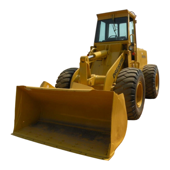
INTRODUCTION SECTION 1 SECTION CONTENTS 1.1. Introduction ..........................3 1.2. Serial Numbers ........................5 DRESSTA OM515C520C99/1E... - Page 13 - Rear of the Machine Fig. 1.2. 520 Series C Wheel Loader a - Right Hand Side of the Machine c - Front of the Machine b - Left Hand Side of the Machine d - Rear of the Machine DRESSTA OM515C520C99/1E...
-
Page 14: General
Failure to follow such instructions may result in damage of the machine and heavy material losses. NOTE: This sign and text in italics is used throughout this manual to call your attention to important function having influence on the right functioning of the machine or for informational purposes. OM515C520C99/1E DRESSTA... - Page 15 The machine serial number plate is located at the bottom of the left hand side of the cab. It is also stamped on the left rear corner of the rear frame. Fig.1.4. Location of stamped machine serial number Fig.1.5. Engine Serial Number Plate DRESSTA OM515C520C99/1E...
- Page 16 All other main components having serial numbers are each equipped with a separate serial number plate or the number is stamped on the component body. Use respective serial numbers when requesting information or ordering parts and proper numbers from Parts Catalogue. OM515C520C99/1E DRESSTA...
-
Page 17: Section 2 Safety Precautions
SECTION 2 SAFETY PRECAUTIONS... -
Page 18: Before Starting The Engine
2.2. Before Starting the Engine ....................4 2.3. Operating the Machine ...................... 4 2.4. General Maintenance Precautions ..................6 2.5. When Parking ........................10 2.6. Safety Graphics Location ....................11 2.6.1. Safety Graphics ..................... 12 2.6.2. Safety Graphics (Version CE) ................16 DRESSTA OM515C520C99/1E... - Page 20 All damaged steps or grab handles should be repaired immediately. Remove or secure all maintenance and personal items so they will not interfere with the operator or jam the controls. DRESSTA OM515C520C99/1E...
- Page 21 Before moving the machine, sound the horn to warn the nearby personnel. Check the brakes, steering and attachment controls. All systems must be fully operative. After starting and while operating, observe instruments and warning lights frequently. Investigate any unusual indications or noises in the machine. OM515C520C99/1E DRESSTA...
- Page 22 Pass other vehicles only when the road is clear and there is enough room and reserve power to pass. Never try to get on or off the machine while it is moving. A serious injury or death could result. DRESSTA OM515C520C99/1E...
- Page 23 Know the traffic flow patterns of the job site. Obey flagmen, signs and signals. There is no substitute for good judgment when working on a slope. Slope operation should be limited according to the ground and traction conditions, the load being carried, and the speed of the machine. OM515C520C99/1E DRESSTA...
-
Page 24: General Maintenance Precautions
Never adjust relief valves higher than the specified pressure because this may damage the machine and lead to injury. When checking pressures, use the correct gauge for the expected pressure. Consult the Authorized Distributor of Construction Equipment DRESSTA OM515C520C99/1E... - Page 25 Tag the cables and controls to warn against starting. Keep the engine exhaust manifold(s) and exhaust system clear of combustible material to reduce the chance of fire. Never remove any guards or shields with the engine running because of the danger of contacting rotating parts. OM515C520C99/1E DRESSTA...
- Page 26 Use a clip-on chuck with a hose long enough to allow person inflating the tire to stand to the side. Serious injure could result if the tire and rim were to separate. DRESSTA OM515C520C99/1E...
-
Page 27: When Parking
5. A wheel loader in CE configuration was given TÜV Hannover Laboratory DE 10-893 641 16 Noise Level Certificate on 17 May 1999. The level of noise produced by a brand new machine reached 104 [dB] (A) when measured according to ISO-6395 standard (admissible value according to EEC/662/86 directive is 107 [dB] (A)). OM515C520C99/1E DRESSTA... -
Page 28: Safety Graphics Location
SAFETY PRECAUTIONS SECTION 2 Page 11 2.6.SAFETY GRAPHICS LOCATION Fig. 2.1. Safety Graphics Location DRESSTA OM515C520C99/1E... -
Page 29: Safety Precautions
Decal 1 - On the rear frame near the center articulation pivot and on the instrument panel in the operator’s cab Decal 2 - On the rear frame near the center articulation pivot Decal 3 - Near the ladders and steps OM515C520C99/1E DRESSTA... - Page 30 SAFETY PRECAUTIONS SECTION 2 Page 13 SAFETY GRAPHICS LOCATION Decal 4 - Near the radiator filler cap Decal 5 - On the hydraulic reservoir Decal 6 - In the operator’s cab DRESSTA OM515C520C99/1E...
- Page 31 SECTION 2 Page 14 SAFETY GRAPHICS LOCATION Decal 7 - In the operator’s cab Decal 8 - In the cab on the side window Decal 9 - In the operator’s cab Decal 10 - On the battery box OM515C520C99/1E DRESSTA...
- Page 32 SAFETY PRECAUTIONS SECTION 2 Page 15 SAFETY GRAPHICS LOCATION Decal 11 - On the battery box DRESSTA OM515C520C99/1E...
- Page 33 Decal 1 - On the rear frame near the center articulation pivot and on the instrument panel in the operator’s cab Decal 2 - On the rear frame near the center articulation pivot Decal 3 - Near the ladders and steps OM515C520C99/1E DRESSTA...
- Page 34 SAFETY PRECAUTIONS SECTION 2 Page 17 SAFETY GRAPHICS LOCATION Decal 4 - Near the radiator filler cap Decal 5 - On the hydraulic reservoir Decal 6 - In the operator’s cab DRESSTA OM515C520C99/1E...
- Page 35 SECTION 2 Page 18 SAFETY GRAPHICS LOCATION Decal 7 - In the operator’s cab Decal 8 - In the cab on the side window Decal 9 - In the operator’s cab Decal 10 - On the battery box OM515C520C99/1E DRESSTA...
- Page 36 SAFETY PRECAUTIONS SECTION 2 Page 19 SAFETY GRAPHICS LOCATION Decal 11 - On the battery box DRESSTA OM515C520C99/1E...
-
Page 37: Machine Transport
SECTION 3 MACHINE TRANSPORT AND STORAGE... -
Page 38: Lifting On Slings
3.1.3. Transportation by Machine Own Drive ..............5 3.2. Lifting on Slings ......................... 5 3.3. Moving a Disabled Machine ....................6 3.4. Machine Storage ....................... 7 3.4.1. Preparing for Storage ....................7 3.4.2. Servicing During Storage ..................9 3.4.3. Preparing for Operation after Storage..............10 DRESSTA OM515C520C99/1E... - Page 40 Fig. 3.1. Frame Locking Bar and Pins Fig. 3.2. Frame Locking Bar and Pins in stowed position in locked position Fig. 3.1.A. Frame Locking Bar and Pins Fig. 3.2.A. Frame Locking Bar and Pins in stowed position (CE version) in locked position (CE version) DRESSTA OM515C520C99/1E...
- Page 41 1. Unscrew and remove bolt (2). 2. Turn bracket (1) into the required position. 3. Reinstall the bolt in hole (3) and tighten. IMPORTANT: It is recommended to change the position of lamps (to fold brackets) before machine transport to prevent damage. OM515C520C99/1E DRESSTA...
- Page 42 6. Detailed information on safety precautions when driving – see "SAFETY PRECAUTIONS”, Section 2. 3.2. LIFTING ON SLINGS Fig. 3.4. Method of Handling 515C Loader by a Crane (for a machine equipped with 15.5R25 Tires and 1.53 [m ]. bucket) 1.
-
Page 43: Moving A Disabled Machine
WARNING: Observe safety precautions specified in this manual. Refer to "SAFETY PRECAUTIONS”, Section 2. Hook a towing line or cable of adequate strength to the towing lug. The towing load should not exceed a force of 80 [kN]. OM515C520C99/1E DRESSTA... -
Page 44: Machine Storage
(if equipped) be stored with a dry cooling system. 7. Drain the water from the fuel tank. Refer to "FUEL TANK", Section 5. Clean the fuel strainer installed in the filler neck. 8. Remove and replace the fuel filters. Refer to "FUEL SYSTEM", Section 5. DRESSTA OM515C520C99/1E... - Page 45 NOTE: When sealing with tape, be sure to extend tape approximately one inch (25 [mm]) beyond an opening to insure good sealing. 19. Pour 60 [ml] VCI to the intake manifold to prevent corrosion of the space between piston and the bottom part of the engine head. OM515C520C99/1E DRESSTA...
- Page 46 3. Install fully charged batteries. Refer to "BATTERIES", Section 5. WARNING: Be sure the electrical system master switch is off when connecting or disconnecting batteries to minimize the chance of sparks and explosion. DRESSTA OM515C520C99/1E...
- Page 47 WARNING: Check that batteries are level in the holders and securely held. The hold-down fasteners should hold the batteries firmly but not too tight to warp or damage either the hold-down bar or batteries. Lay the cables so they do not chafe against the hold-down bar or the fasteners. OM515C520C99/1E DRESSTA...
- Page 48 Once the engine is running, move the machine outdoors as soon as possible. Exhaust gases are dangerous and can cause unconsciousness and death. 13. Start the engine, refer to "STARTING AND STOPPING THE ENGINE”, Section 4 and "SCHEDULED MAINTENANCE GUIDE” recommendations (daily service), Section 5. DRESSTA OM515C520C99/1E...
-
Page 49: Section 4 Operating
SECTION 4 OPERATING... - Page 50 4.20.2. Quickcoupling with a 2-Spool Valve ..............56 4.21. Ride Stabilizing Mechanism ..................... 56 4.21.1. Driving a Machine equipped with RMS System ............57 4.22. High-Dump Bucket ........................57 4.22.1. High-Dump Bucket Control ..................57 4.22.2. Operating the High-Dump Bucket ................57 DRESSTA OM515C520C99/1E...
- Page 52 When towing with a long chain or cable, take up the slack slowly to avoid jerking. Before shutting down operate the engine at idle (no load) for 3 to 5 minutes. This will aid in cooling the engine and turbocharger. DRESSTA OM515C520C99/1E...
-
Page 53: Universal Symbols For Instruments And Controls
Study the following symbols so you will know their meaning immediately and at a glance. NOTE: Some symbols may not pertain to your machine. OM515C520C99/1E DRESSTA... -
Page 54: Instruments And Controls
OPERATING SECTION 4 Page 5 UNIVERSAL SYMBOLS FOR INSTRUMENTS AND CONTROLS Fig. 4.1. Universal Symbols for Instruments and Controls DRESSTA OM515C520C99/1E... - Page 55 OPERATING SECTION 4 Page 6 UNIVERSAL SYMBOLS FOR INSTRUMENTS AND CONTROLS OM515C520C99/1E DRESSTA...
- Page 56 47. Hydraulic Oil Level 48. Hydraulic Oil Pressure Diagnostic Point 49. Hydraulic Oil Filter 50. Test 51. Brake Fluid Fill 52. Brake Fluid Level 53. Battery Charge Indicator 54. Battery Disconnect 55. Voltmeter 56. Road Lights 57. Low Level Lights DRESSTA OM515C520C99/1E...
- Page 57 Before operating the machine you must be thoroughly familiar with the location and use of all instruments and controls. WARNING: Understand all control functions before starting the engine. Each reference number in the illustrations of this section has a corresponding reference number and explanation in the text. OM515C520C99/1E DRESSTA...
- Page 58 10. Rear Parking and Front Work Lights Switch (Front, Rear Parking Lights/Low Beam Lights Switch in CE Version) 11. Work Lights Switch (Front and Rear Work Lights Switch in CE Version) and Bulb Check Switch 11A. Emergency Lights Switch DRESSTA OM515C520C99/1E...
- Page 59 (the pointer should stay within the green area of the meter). The gauge pointer should also remain in the green area under full load conditions. If the temperature remains too high in spite of interruptions of engine operation, check the coolant level, the condition of the radiator, fan, water pump and thermostat. OM515C520C99/1E DRESSTA...
- Page 60 Midposition between RUN and START - warning lights check - activates all warning lights, IMPORTANT: Do not hold the key in START position for more than 30 second. Allow a 2–3 minute interval between cranking. Never place the key in START position when engine is running. DRESSTA OM515C520C99/1E...
- Page 61 If the light stays on, stop the machine and run the engine until the temperature drops to app. 90 [° ° C]. Find the reason of oil overheating: • transmission oil low level, • dirty radiator, • dirt suction filter. OM515C520C99/1E DRESSTA...
- Page 62 This switch locks the transmission direction lever in its neutral position if shifted into the furthest left position. To release the lock, shift it to the right. 22A. RSM System Switch This switch has 2 positions: ON - the ride stabilizing system is switched on, OFF - the ride stabilizing system is switched off. DRESSTA OM515C520C99/1E...
- Page 63 33 - Brake and Transmission Disconnect Pedal 34 - Hydraulic Pilot Control Valve Lock Switch 35 - Control Levers Lock Plate (Fig. 4.7) 36 - Float Position Lock Switch 37 - Bucket and Boom Pilot Control Valve Lever OM515C520C99/1E DRESSTA...
-
Page 64: Operator's Seat
• when shifted forward it locks the quickcoupling, • when shifted back it unlocks the quickcoupling. 29. ACCELERATOR PEDAL Depress the pedal to increase engine speed, release the pedal to decrease engine speed. Pedal returns automatically to the low idle position. DRESSTA OM515C520C99/1E... - Page 65 WARNING! Do not press the transmission disconnect pedal when traveling fast or going downhill because this shifts the transmission into neutral. Loss of control or damage to the power train could result when the pedal is released and transmission re-engages. OM515C520C99/1E DRESSTA...
- Page 66 This switch has 2 positions: • ON: keeps the boom in the float position, • OFF: releases the float position lock. Fig. 4.8. Hydraulic Pilot Control Lever Lock Switch (34) and Pilot Valve "Float" Position Lock Switch 1. ON 2. OFF DRESSTA OM515C520C99/1E...
- Page 67 41. WINDSHIELD WIPER CONTROL SWITCH This switch controls the speed of the windshield wiper motor. It has three positions: • OFF, • LO, • HI. Move the switch to the desired position for low or high speed wiper operation. OM515C520C99/1E DRESSTA...
- Page 68 However, should the brake system ever fail, the parking brake may be used to make an emergency stop. IMPORTANT: Release the parking brake before moving the machine. The brake could burn or be damaged if the machine is driven with it applied. Fig. 4.10. Parking Brake Lever DRESSTA OM515C520C99/1E...
- Page 69 The cab door may be locked in an open position. The latch is particularly useful for cab ventilation when operating in high ambient temperatures. The latch will be released automatically if the door is pulled energetically to close. OM515C520C99/1E DRESSTA...
- Page 70 The height can be adjusted by removing the bolts that secure the inner post to the outer post and lining up the holes in both posts at a higher or lower setting. Be sure to put in and tighten the bolts. DRESSTA OM515C520C99/1E...
-
Page 71: Seat Belt
Release the cushion allowing the catches on the seat back to engage in bracket notches (2).The suspension preload should be adjusted to the operator’s weight for proper ride control. While sitting in the seat, turn ratchet lever (1) clockwise to increase the preload. Turn the ratchet counterclockwise to decrease the preload. OM515C520C99/1E DRESSTA... - Page 72 (5) to change the lower and upper part of the backrest profile. Armrest angle adjustment – performed with screws (6) located under the armrests (tilt back the armrests to facilitate adjustment). DRESSTA OM515C520C99/1E...
- Page 73 1. To shorten the belt, pull the free end of the belt at either the buckle or tang end or at both ends. 2. To lengthen the belt, pull the belt while holding it at a right angle to the buckle or tang. OM515C520C99/1E DRESSTA...
-
Page 74: Cab Heating And Ventilation
4.7.2. HEATER For cab heating, ventilation and air conditioning integrated heater and air conditioner installed in the right hand side of the cab wall is used. The heater and air conditioner controls are situated in the side control panel. DRESSTA OM515C520C99/1E... - Page 75 The a/m components are connected with hoses 6 – 9. The A/C system is filled with R-134A gas. NOTE: If A/C system refilling is required contact Construction Equipment Authorized Distributor. The system must be filled in accordance with the manufacturer’s instructions. OM515C520C99/1E DRESSTA...
-
Page 76: Air Cleaner Service Indicator
CE version the switch is located at the back on the left hand side. WARNING: Before servicing the machine, turn off the electric system master switch and remove the key. Tag the machine to warn against starting the engine. DRESSTA OM515C520C99/1E... -
Page 77: Dome Lights With Switches
6. Turn the starting key from RUN to START position (Fig. 4.3) to start the engine with accelerator pedal released (idle speed). 7. Keep the key till the engine starts but no longer than 30 seconds. Then release the key immediately, it returns automatically to the RUN position. OM515C520C99/1E DRESSTA... - Page 78 Never puncture the fluid container or put it into fire. Dispose of empty containers properly. h) For your safety, remove the ether container when welding, grinding, or using a torch on the machine. I) Follow the correct method for starting the engine. DRESSTA OM515C520C99/1E...
-
Page 79: Driving The Machine
OM515C520C99/1E DRESSTA... - Page 80 (2) in the desired position forward or reverse. NOTE: If the machine is equipped with a back-up warning alarm, the alarm will sound when the lever is placed in reverse. 7. Release brake pedal (3) and gradually depress accelerator pedal (4). DRESSTA OM515C520C99/1E...
-
Page 81: Shifting Gears
Turn the steering wheel until reaching the desired angle of turn. Hydraulic power holds the angle of the turn until the steering wheel is turned again. WARNING! Never allow anyone near the center articulation pivot with engine running. OM515C520C99/1E DRESSTA... -
Page 82: Stopping The Machine
When parking a machine: stop the engine, lower the bucket to the ground, lock the transmission shift lever in neutral (N), apply the parking brake, turn off the electric system master switch, and remove the keys. DRESSTA OM515C520C99/1E... -
Page 83: Parking The Machine
4.17.1. BOOM CONTROL LEVER POSITIONS (Fig. 4.28.) Fig. 4.28. Boom Control Lever Positions (Standard Version) A. Raise B. Hold C. Lower D. Float OM515C520C99/1E DRESSTA... - Page 84 Push the lever all the way forward for this position. This position is detented so the lever must be pulled back manually to the "hold" position. Use the “float" position to follow the contour of the ground when leveling or to lower the boom by gravity. DRESSTA OM515C520C99/1E...
- Page 85 WARNING! Use extra caution when adjusting loader’s bucket leveler or boom kick-out. Use two trained people and guard against accidental movement of the machine or loader linkage. No personnel is allowed within the reach of loader linkage. Never work or walk under raised bucket without proper blocking. OM515C520C99/1E DRESSTA...
- Page 86 To dump the bucket, push the lever: a) in standard version: all the way forward, b) in upgraded version; to the right, away from the operator. When the lever is released, it will automatically return to hold position B. DRESSTA OM515C520C99/1E...
- Page 87 HOLD The control lever will return automatically to the "HOLD" position from either the "OPEN" or "CLOSE" position when released. The bucket clam will remain in the same position it was in when the control lever was released. OM515C520C99/1E DRESSTA...
- Page 88 To set the multi-purpose bucket as a scraper, open the clam until the indicator points to "2" or "4" on the clam product graphic (A, Fig. 4.34). The more the clam is open, the deeper a cut can be made. Fig. 4.34. Multi-purpose Bucket set in "Scraper" Position. A. Clam Product Graphic DRESSTA OM515C520C99/1E...
- Page 89 Position "A", Fig. 4.36 is for level grading. Position "B", Fig. 4.36 is for a deeper cut and position "C", Fig. 4.36 is for a lesser amount of cut. Fig. 4.36. "Dozer Blade Pitch" Position. A. Clam Product Graphic OM515C520C99/1E DRESSTA...
-
Page 90: Loader Techniques
Fig. 4.39. Keep the trucks close to the work area to minimize loader travel. Keep work areas clean and level. When possible, spot the next truck to be loaded on the opposite side as shown in Fig. 4.38. DRESSTA OM515C520C99/1E... - Page 91 Back away in an arc from the bank or stockpile as shown in Fig. 4.38 and 4.39 just far enough to allow turning of the loader for the approach to the truck. Fig. 4.40. Bank Loading (Working into Material) OM515C520C99/1E DRESSTA...
- Page 92 3. To use a multi-purpose bucket as a bucket, roll the bucket forward or backward and move the machine forth. The cutting edge will penetrate into the ground till the clam’s cutting edge gets into full contact with the ground (Fig. 4.43). Fig. 4.43. Starting to Load DRESSTA OM515C520C99/1E...
- Page 93 The higher gear range may be used for making return trips to the loading sites. WARNING! Transport loads with bucket in the carry position only. A loaded bucket must never be transported in the fully raised boom or with boom in horizontal position. OM515C520C99/1E DRESSTA...
- Page 94 Using the automatic boom kick-out and bucket leveler is particularly recommended in continuous operation of even working cycle. For this kind of operation the positioning of the truck receiving the spoil is of importance. Fig. 4.48. Dumping Into Truck DRESSTA OM515C520C99/1E...
- Page 95 It may be necessary to raise the lift arms slightly to obtain greater traction. Less loading effort is required when the material can be moved downhill. WARNING! Never travel with an unstable and solid rock. OM515C520C99/1E DRESSTA...
- Page 96 WARNING! Never backdrag, push any objects (trees, rocks, etc) with the bucket in the utmost dump position as due to unfavorable distribution of forces a serious damage to loading mechanism can result. It is particularly unfavorable when operating with boom raised. DRESSTA OM515C520C99/1E...
- Page 97 This will require ripping each section only once, not every morning after the ground has refrozen. To prevent breaking or bending scarifier teeth, never turn the loader while the scarifier teeth are in the ground. Fig. 4.54. Bulldozing with Multi-purpose Bucket OM515C520C99/1E DRESSTA...
- Page 98 Heavy roots of large trees may require cutting from several sides of the tree (Fig. 4.56). Use a cable to topple and remove trees from soft ground. Topple the tree, back the loader and lower the bucket to the ground and push the tree from the site. Fig. 4.56. Removing Large Trees DRESSTA OM515C520C99/1E...
- Page 99 When finishing a non-solid material, position the bucket as shown in Fig, 4.58 or Fig. 4.59 and backdrag the loose material. This method is not recommended where abrasive material is common. Fig. 4.58. Backdragging and Leveling Fig. 4.59. Backdragging and Leveling with Multi-Purpose Bucket OM515C520C99/1E DRESSTA...
- Page 100 The following illustrates some of the ways a multi-purpose bucket should NOT be used. DO NOT use roll back force to pull stumps or buried objects from the ground – it may bend the clam (Fig. 4.63). DRESSTA OM515C520C99/1E...
- Page 101 Fig. 4.65. Side Loading the Clam against an Fig. 4.66. Uneven Stress to Clam Anchored Object DO NOT clamp objects on only one side of the clam. It causes uneven stresses and may twist the clam out of the line (Fig. 4.66). OM515C520C99/1E DRESSTA...
- Page 102 Do not charge a bank with an object caught between the clam and blade (Fig. 4.69). This can twist the clam out of alignment. DO NOT use the bottom of the clam as a pile driver (Fig. 4.70). This will bend the clam. DRESSTA OM515C520C99/1E...
-
Page 103: Quickcoupling
The hydraulic schematic of a 520 C loader equipped with a 3-spool control valve is shown in Section 6. The hydraulic schematic of a 520C loader equipped with a 2-spool control valve and a pilot solenoid valve (standard and upgraded version) is shown in Section 6. OM515C520C99/1E DRESSTA... - Page 104 • unlock the equipment from the tool carrier (see PIN UNLOCKING above), • shift the bucket control lever into the dumping position slowly backing the machine away so as to drive the tool carrier away from the mounted equipment DRESSTA OM515C520C99/1E...
-
Page 105: Ride Stabilizing Mechanism
Ride stabilizing mechanism is a hydraulic system consisting of a block of hydraulic valves and accumulators preset for a pressure of 1.6 [MPa] (16 [bars]) (there are 5 accumulators in 515C and 6 in 520C loader). All the components are built-in in the loader’s front frame. -
Page 106: High-Dump Bucket
4.22. HIGH-DUMP BUCKET The high-dump bucket is one of optional auxiliary equipment mounted on a 515C loader fitted with a 3-spool control valve. The assembly consists of a bucket, bucket frame and cylinders. The assembly is installed on the boom. Any other bucket can be installed instead of the high-dump bucket (Refer to HIGH-DUMP BUCKET, Section 6). -
Page 107: Section 5 Maintenance
SECTION 5 MAINTENANCE... -
Page 108: General Precautions
5.10.3. Bulb and Lamp Replacement ................. 29 5.10.4. Batteries ........................29 5.11. Engine ........................... 31 5.11.1. Checking the Crankcase Oil Level ................. 31 5.11.2. Changing the Crankcase Oil and Filter ..............32 5.11.3. Checking the Condition and Tension of Belts ............33 DRESSTA OM515C520C99/1E... - Page 109 5.20. Hood Assembly and Radiator Grill ..................54 5.21. Loader Equipment ......................... 55 5.22. Air Conditioner or Heater (if Equipped) .................. 56 5.22.1. Inside Filter ......................56 5.22.2. Outside Filter ......................57 5.22.3. Air Conditioner Off Season Care ................57 OM515C520C99/1E DRESSTA...
-
Page 110: Scheduled Maintenance Guide
Scheduled maintenance is a normal procedure necessary to provide a machine’s proper operation. WARNING! For your personal safety carry out all maintenance service in accordance with specified scheduled maintenance guide and instructions. To prolong the service life of your equipment follow the scheduled maintenance listed in 5.2. and 5.3. DRESSTA OM515C520C99/1E... - Page 111 3. Check the wheel mounting hardware for torque. Refer to 5.17. 4. Check the operation of the parking brake. Refer to 5.7.5. 5. Check the drive axles (differential and planetaries) oil level. Refer to 5.9.1. 6. Change the engine crankcase oil and engine oil filter. Refer to 5.11.2. OM515C520C99/1E DRESSTA...
- Page 112 9. Replace the ether container (if empty). Refer to 5.12. (optional attachment). 10. Lubricate: − the control levers, − the pedals, − the superstructure and cab hinges, etc. Refer to 5.4.7. 11. Clean the air conditioner or heater filters (if equipped). Refer to 5.22. DRESSTA OM515C520C99/1E...
-
Page 113: Lubrication
Ground Level Inspection Check Brake Fluid Level Check Radiator Coolant Level Check Engine Crankcase Oil Level Every HDTF/EO2 Check Hydraulic Reservoir Oil Level 10 Hours Check Transmission Oil Level HDTF Drain Water Fuel Tank and Sediment Water Separator OM515C520C99/1E DRESSTA... - Page 114 MPG1 – Muli-Purpose Grease, Grade 1 MPG2 – Muli-Purpose Grease, Grade 2 ATF – Automatic Transmission Fluid HDTF – Hydraulic and Transmission Fluid MPL - Multigrade Transmission Oil (s) – for standard machines (u) – for upgraded machines DRESSTA OM515C520C99/1E...
- Page 115 MAINTENANCE SECTION 5 Page 8 MAINTENACE AND SERVICE CHART 5.3.1. SERVICE POINTS Fig. 5.1. Service Lube Points Service point description is given in Chart 1. OM515C520C99/1E DRESSTA...
- Page 116 During cold weather, base the selection of a crankcase lubricating oil viscosity on the lowest anticipated temperature for the day to make starting easier. For hot weather operation, base the selection on the highest anticipated temperature. Refer to the "REFILL SPECIFICATIONS AND CAPACITIES", Section 5.4.5, Chart 2. DRESSTA OM515C520C99/1E...
- Page 117 Capacity [l] Lubrication Temp. Temp. Temp. Grade 515C 520C +49[° ° C] to –7[° ° C] +21[° ° C] to –23[° ° C] – 12[° ° C] to –34[° ° C] point Engine Oil per B21-0002 CE/SG per API Crankcase 16.4...
- Page 118 ASTM D875 DP: above - 12 [°C] 1D: above - 12 DZ: above - 20 [°C] 2D: above - 20 IZ-40: above - 30 [°C] DFA: below - 30 For temperatures below - 30 [°C] add depressant DRESSTA OM515C520C99/1E...
- Page 119 MAINTENANCE SECTION 5 Page 12 LUBRICATION 5.4.7. LUBRICATING FITTINGS (LUBRICATED WITH SOLID GREASE) Fig. 5.2. Lubricating Points (fittings) Fig. 5.2A. Multi-Purpose and High-dump Bucket Lubricating Points Service point description is given in Chart 2. OM515C520C99/1E DRESSTA...
- Page 120 17 Clam Hinge Pins, 1 point on each side High-dump Bucket Hinge Pins 1 point on each side 18 Clam Cylinder Lower Pins, 1 point on each side High-dump Bucket Cylinder Lower Pins 1 point on each side DRESSTA OM515C520C99/1E...
-
Page 121: Seasonal Preparations
Refer to Section 5.8.6. 5.5.3. ELECTRICAL SYSTEM Clean batteries and remove all corrosion from the battery terminals and cables. Repair or replace all wires which have worn, cracked or frayed insulation and broken or loose wires. Service the batteries. OM515C520C99/1E DRESSTA... -
Page 122: Air Cleaning System
IMPORTANT: Be careful not to dislodge dust from the dirty element onto the safety element. 4. Remove all dirt from inside air cleaner body (5) with a damp cloth. A small amount of nonsudsing detergent added to the water will remove the soot. DRESSTA OM515C520C99/1E... - Page 123 Inspection of the element on the outside will disclose any holes where concentrated light shines through. The slightest rupture requires replacement of the filter element. 2. Inspect the contact surfaces of the air cleaner body. If faulty or damaged surfaces are noted, correct these conditions immediately. OM515C520C99/1E DRESSTA...
- Page 124 Loosen clamp screw (3, Fig. 5.5) on the precleaner hood. Twist and pull upward to remove the cap. Use compressed air to clean the screen. If compressed air is not available, wash in clean hot water or water containing a small amount of nonsudsing detergent. DRESSTA OM515C520C99/1E...
- Page 125 C) all clamped hose and gasket connections between the air cleaner outlet and the intake manifold including turbocharger connections, D) the surface of all air induction hoses, the air cleaner and air intake manifold, 6. No leakage is permitted between air cleaner and intake manifold (the entire air induction OM515C520C99/1E DRESSTA...
-
Page 126: Brakes
Consult your distributor. 5.7.2. CHECKING THE BRAKE FLUID LEVEL Fig. 5.6. Master Brake Cylinder Sight Gauge (under the floorboard) Check the sight gauges on the master cylinder (Fig. 5.6). The sight gauges must be completely filled with fluid. DRESSTA OM515C520C99/1E... - Page 127 3. Pressing the brake pedal pump the brake fluid out of the circuit into the container till all the fluid has flown out and air escapes from the circuit. 4. If necessary, (i.e. if still some fluid has remained in the master cylinder), disconnect the lines from the master cylinder and drain the remaining fluid. OM515C520C99/1E DRESSTA...
- Page 128 “NEUTRAL”, lower the bucket to the ground, and stop the engine. WARNING! If the parking brake does not hold the machine stationary correct the cause. Until the cause is corrected, park the machine on level ground and block the tires to prevent it from moving. DRESSTA OM515C520C99/1E...
-
Page 129: Cooling System
Softened water that is prepared using common salt (sodium chloride) contains excessive amounts of chlorides and should not be used. OM515C520C99/1E DRESSTA... - Page 130 WARNING! Hot, scalding coolant can spray out if the radiator cap is removed suddenly. Relieve system pressure by slowly turning the cap to the first notch or lifting the safety lever (if equipped). Remove the cap only after the pressure is relieved. DRESSTA OM515C520C99/1E...
- Page 131 (in CE version the access to the gauge is gained after lifting the radiator grill, 1, Fig. 5.48A). 2. Add coolant if it must be added; remove the radiator cap as outlined above (Fig. 5.9). 3. Add coolant until the level in sight gauge in reached. 4. Reinstall the radiator cap. OM515C520C99/1E DRESSTA...
- Page 132 7. Close the cab heater water valve on the engine. 8. Check all the hoses and clamps for damage and the radiator for leaks and damage. If the system is contaminated, it must be cleaned as described below. DRESSTA OM515C520C99/1E...
- Page 133 3. Start the engine and run it idle until the normal operating temperature is reached. Add coolant as needed to keep the level to the neck of the radiator visible in the sight gauge. 4. After all air is removed and level remains fixed, install the radiator cap and check the system for leaks. OM515C520C99/1E DRESSTA...
-
Page 134: Drive Axles
2. Remove the filler plug on either the front or rear axle. The oil must reach the lower edge of the plug hole. Add lubricant until it starts flowing from the hole. Refer to “REFILL SPECIFICATIONS AND CAPACITIES CHART” for the type of lubricant specified. Fig. 5.13. Axle Level and Filler Plug 3. Install the filler plug. DRESSTA OM515C520C99/1E... - Page 135 6. Fill the axle with fresh lubricant through the fill hole in the axle until the lubricant starts to flow from the hole. 7. Install the filler and inspection plugs. Fig. 5.15. Axle Drain and Brake Inspection Plugs 1. Brake Drain Plug 2. Brake Inspection Plug OM515C520C99/1E DRESSTA...
-
Page 136: Electrical System
Never allow the battery to stand on concrete, ground or a metal support unless proper insulation is provided. A wooden platform or board is sufficient insulation. Be sure the battery is fastened securely to avoid damage from vibration. DRESSTA OM515C520C99/1E... -
Page 137: Engine
(ground) cable of the booster battery to the machine frame. Be sure the negative cable is 300 [mm] or more away from the battery. The parking brake should be applied, and transmission lever locked in neutral position. OM515C520C99/1E DRESSTA... - Page 138 15 minutes after stopping it. This allows the oil to drain back to the crankcase. IMPORTANT: Park the loader on level ground for correct oil level reading. Fig. 5.16. Checking the Crankcase Oil Level Fig. 5.17. Engine Oil Dipstick 1. Dipstick 2. Filler Port DRESSTA OM515C520C99/1E...
- Page 139 Remove the castellated nut protecting the automatic valve. Install the drain valve on the open thread. The drain valve will be opened automatically as the hose nut is threaded in. Fully threaded nut opens the valve completely. Fig. 5.19. Lubricating Oil Filter (LH Side of Machine) OM515C520C99/1E DRESSTA...
- Page 140 Fig. 5.20. Belt Inspection Check belt tension midway between the pulleys every 1000 hours of operation. Application of a force of 270 to 580 [N] should cause deflection of a belt of 9.5 – 12.7 [mm] at the most. DRESSTA OM515C520C99/1E...
- Page 141 Check the fan to make sure it is securely mounted. Replace any fan that is damaged. Check the fan hub every 1000 hours of operation. It should rotate freely although without excessive loose. Fig. 5.22. Checking for Fan Defects OM515C520C99/1E DRESSTA...
- Page 142 3. Position the first cylinder piston in the top dead center (TDC) by turning the pinion on the rack by hand and simultaneously pressing the timing pin (Fig. 5.25). When the pin slides into the camshaft hole/opening, the cylinder piston has reached the top dead center (TDC). DRESSTA OM515C520C99/1E...
- Page 143 1. Suction Valves 2. Exhaust Valves 5. Mark the position of the vibration damper, rotate it by 360 [º]. Check and adjust, if necessary, the other valves as shown in Fig. 5.27 as described in item 4 above. OM515C520C99/1E DRESSTA...
-
Page 144: Ether Injector
Make certain that ether is available under pressure. To do so, remove the ether container and check if a good spray is obtained. If not, replace with a new container. If a good spray was obtained. Install the container and test the ether injector as follows: DRESSTA OM515C520C99/1E... -
Page 145: Fuel System
WARNING! Never mix gasoline, gasohol (a mixture of corn alcohol and 90 % gasoline), or alcohol with diesel fuel. This creates a fire or explosion hazard which could result in personal injury or death. OM515C520C99/1E DRESSTA... - Page 146 O-ring. Clean the fitter gasket surfaces of the filter header for each filter (Fig. 5.31). Fill the new filters with clean diesel fuel. Install the new O-ring supplied with a filter. Then apply a thin coat of clean engine oil to the seal of the filter. Install the filters on the filter header. DRESSTA OM515C520C99/1E...
- Page 147 • stop the engine, • turn the water separator drain valve to the left by 1.5 to 2 turns, • drain the water until clear fuel start to flow, • close the valve by turning home to the right. OM515C520C99/1E DRESSTA...
- Page 148 2. Crank the engine till clean fuel appears. NOTE: While cranking keep away from the rotating engine parts. 3. Torque the high pressure line nut to 24 [Nm]. 4. Start the engine and run it at low idle till the system is vented (smooth operation) DRESSTA OM515C520C99/1E...
-
Page 149: Hydraulic System
3. Check the oil level sight gauge. If the ball is not floating in the sight gauge (Fig. 5.34), oil must be added. WARNING! This machine has a pressurized hydraulic reservoir. Loosen the filler cap slowly to release the pressure. It is obligatory before disassembly of any hydraulic system components. OM515C520C99/1E DRESSTA... - Page 150 2. O-Ring 10. Drain Valve 3. Filler Neck 11. Adapter 4. Filler Cap Assembly 12. O-Ring 5. Breather 13. Sight Gauge 6. O-Ring 14. O-Ring 7. Hydraulic Oil Return Filter 15. Filler Cap Gasket 8. Latch 16. Filler Cap DRESSTA OM515C520C99/1E...
- Page 151 14. Start the engine and operate the boom and bucket to fill the hydraulic cylinders with oil. 15. Lower the bucket to the ground and shut down the engine. Check the oil level as described in section 5.14.1. Fig. 5.36. Boom Safety Valve (on RH Side of Machine) 1. Valve Lever OM515C520C99/1E DRESSTA...
- Page 152 2. Remove old element (1) and replace it with a new one. 3. Clean the dismantled parts and install cover (3). Fig. 5.37. Hydraulic Reservoir Return Filter 1. Filter Element 3. O-Ring 5. O-Ring 2. Indicator Assembly 4. Filter Header 6. Indicator DRESSTA OM515C520C99/1E...
- Page 153 4. Check seal rings (3) for wear or deterioration. Replace if necessary. 5. Reinstall filter (5) (cleaned or new) and cover (4). Secure with ring (2). 6. Tighten the reservoir filler cap. Fig. 5.38. Hydraulic Reservoir Breather 1. Cap 2. Retaining Ring 3. Filter Seal 4. Cover 5. Filter OM515C520C99/1E DRESSTA...
- Page 154 Never vent built-up pressure in a tire, such as encountered on hot days. Pressure build-up on hot days actually protects the tires by avoiding excessive sidewall flexing and its overheating, which are detrimental to tire life. Venting tires will also result in underinflation when the tires cool. DRESSTA OM515C520C99/1E...
-
Page 155: Transmission System
2. Lock the transmission in "N" (neutral), lower the bucket to the ground and apply the parking brake. 3. Check the oil level in lower sight gauge (2, Fig. 5.41) through a cut-out in the rear frame left wall. OM515C520C99/1E DRESSTA... - Page 156 4. Unscrew transmission oil filler cap (2, Fig. 5.41). This will vent the case and allow the oil to drain faster. 5. While the oil is draining, service the transmission pressure filter element. Refer to Par. 5.18.3. 6. Service the transmission suction strainer. Refer to Par. 5.18.4. DRESSTA OM515C520C99/1E...
- Page 157 12. Install drain plug (3) and O-ring (2) into the case. 13. Start the engine and run it idle for about 5 minutes. Stop the engine and check all connections for leaks. Correct if necessary. 14. Check the transmission oil level (Refer to Par. 5.18.1). OM515C520C99/1E DRESSTA...
- Page 158 5. Install the new element by turning it clockwise in the head till it contacts filter head (4). 6. Make aligning marks on the filter and the filter head and then give the filter an additional 1 to 1.5 turns. DRESSTA OM515C520C99/1E...
- Page 159 3. Dry the breather thoroughly using compressed air. If compressed air is not available, shake to remove the excess cleaning solvent. 4. Dip the cap in clean engine oil. Allow the excess oil to run out. 5. Reinstall the breather. OM515C520C99/1E DRESSTA...
-
Page 160: Rops Cab And Rops Canopy
Fig. 5.47. ROPS Cab Mounting 1. Bolts (3 on Each Side) Check periodically or once a year the torque of ROPS cab mounting bolts (320 [Nm]). Check and torque, if necessary, rearview mirrors, wipers, guards, screens and covers. DRESSTA OM515C520C99/1E... -
Page 161: Hood Assembly And Radiator Grill
5.20. HOOD ASSEMBLY AND RADIATOR GRILL Ample access to the engine compartment is provided by two side doors in 515C loaders. The doors are opened by pulling handles 1 and lifting the doors up. The doors are held in this position by two gas springs. -
Page 162: Loader Equipment
1. Park the machine on level ground or in the workshop. 2. Place the bucket in position as shown in Fig. 5.49. 3. Remove bolts (1) and tap pins (2) out. 4. Move away with the machine or lift the boom. DRESSTA OM515C520C99/1E... -
Page 163: Air Conditioner Or Heater
2. Remove the filter from the cover. 3. Wash the filter in warm water with a small amount of nonsudsing detergent. Rinse the filter in clean water and dry it thoroughly. 4. Reinstall the filter in the housing and reinstall the cover. OM515C520C99/1E DRESSTA... - Page 164 5.22.3. AIR CONDITIONER OFF SEASON CARE The system should be operated for 5 to 10 minutes each week in the off season. The temperature control should be turned to maximum cold position during this 5 to 10 minute run. DRESSTA OM515C520C99/1E...
-
Page 165: Section 6 Specifications
SECTION 6 SPECIFICATIONS... -
Page 166: Application
6.1. Application ..........................3 6.2. Technical Description ......................3 6.3. Schematic of 515C and 520C Wheel Loader Drive Train ............4 6.4. Schematic of Transmission Hydraulic System ..............5 6.5. Loader Equipment and Steering Hydraulic System Schematic ..........6 6.6. - Page 168 Page 3 6.1. APPLICATION 515C and 520C Wheel Loaders are modern machines of C series (i.e. second upgrade) featuring the following foredesign criteria: optimization of performance, long service life, reliability, maximum unification of parts and assemblies, simplified maintenance and serviceability. These general...
-
Page 169: Schematic Of 515C And 520C Wheel Loader Drive Train
It features excellent capacity, breakout force and resistance to dynamic loads ensuring high operational durability and reliability. 6.3. SCHEMATIC OF 515C AND 520C WHEEL LOADERS DRIVE TRAIN Fig. 6.1. 515C and 520C Wheel Loaders Drive Train Schematic 1. -
Page 170: Schematic Of Transmission Hydraulic System
SECTION 6 Page 5 6.4. SCHEMATICS OF TRANSMISSION HYDRAULIC SYSTEM Fig. 6.2. Schematic of 515C Loader Transmission Hydraulic System Fig. 6.2A. Schematic of 520C Loader Transmission Hydraulic System The description of the drive train assemblies shown in Fig. 6.2. and 6.2A 1. -
Page 171: Loader Equipment And Steering Hydraulic System Schematic
6.5. LOADER EQUIPMENT AND STEERING HYDRAULIC SYSTEM SCHEMATIC Fig. 6.3 shows the hydraulic system of the 515C and 520C loader equipped with a 2-spool control valve (standard version). Fig. 6.4 shows the hydraulic system of the standard 515C and 520C loader equipped with a 3-spool control valve (standard version). - Page 172 SPECIFICATIONS SECTION 6 Page 7 LOADER EQUIPMENT AND STEERING HYDRAULIC SYSTEM SCHEMATIC Fig. 6.4. Loader Equipment and Steering Hydraulic System Schematic (Standard 515C and 520C Loader with 3-spool Control Valve) DRESSTA OM515C520C99/1E...
- Page 173 LOADER EQUIPMENT AND STEERING HYDRAULIC SYSTEM SCHEMATICS The description of the assemblies shown in hydraulic system schematic, Fig. 6.3 (standard 515C and 520 C loader with 2-spool control valve), 6.4 (standard 515C and 520 C loader with 3-spool control valve): 1.
- Page 174 SPECIFICATIONS SECTION 6 Page 9 LOADER EQUIPMENT AND STEERING HYDRAULIC SYSTEM SCHEMATIC Fig. 6.5. Loader Equipment and Steering Hydraulic System Schematic (515C and 520C Upgraded Loaders with 2-spool Control Valve) DRESSTA OM515C520C99/1E...
- Page 175 SECTION 6 Page 10 LOADER EQUIPMENT AND STEERING HYDRAULIC SYSTEM SCHEMATIC The description of the assemblies shown in hydraulic system schematic, Fig. 6.5. (515C and 520C upgraded loaders with 2-spool control valve): 1. Return Filter 2. Return Filter Check Valve 3.
- Page 176 SECTION 6 Page 11 LOADER EQUIPMENT AND STEERING HYDRAULIC SYSTEM SCHEMATIC The description of the assemblies shown in hydraulic system schematic, Fig. 6.5A (515C and 520C Upgraded Loaders with 3-spool Control Valve): 1. Return Filter 2. Return Filter Check Valve 3.
- Page 177 SPECIFICATIONS SECTION 6 Page 12 LOADER EQUIPMENT AND STEERING HYDRAULIC SYSTEM SCHEMATIC Fig. 6.5A. Loader Equipment and Steering Hydraulic System Schematic (515C and 520C Upgraded Loaders with 3-spool Control Valve) OM515C520C99/1E DRESSTA...
- Page 178 SPECIFICATIONS SECTION 6 Page 13 LOADER EQUIPMENT AND STEERING HYDRAULIC SYSTEM SCHEMATIC Fig. 6.5B. 515C and 520C Loaders RMS Hydraulic System Diagram 1. RSM Module 2. Hydraulic Accumulators (515C - 5 pcs) (520C - 6 pcs) 3. Shut-off Valve DRESSTA...
-
Page 179: Wiring Diagram
51. Hourmeter 52. Cluster Gauge 53. *Ether Start Switch 55. *Tachometer or Speedometer *Optional attachment equipped on order. NOTE: The wiring diagram represents the system inactive, i.e. while the machine is parked and the master switch is off. OM515C520C99/1E DRESSTA... - Page 180 SPECIFICATIONS SECTION 6 Page 15 WIRING DIAGRAMS Fig. 6.6. Wiring Diagram (Standard 515C and 520C Loaders) DRESSTA OM515C520C99/1E...
- Page 181 SPECIFICATIONS SECTION 6 Page 16 WIRING DIAGRAMS OM515C520C99/1E DRESSTA...
- Page 182 SPECIFICATIONS SECTION 6 Page 17 WIRING DIAGRAMS DRESSTA OM515C520C99/1E...
- Page 183 4 1 T / P 1 / R 1 / R 4 1 T / P 1 9 0 / O 4 1 / P 4 5 F R / B R Fig. 6.7. Wiring Diagram (515C and 520C Upgraded Loader) OM515C520C99/1E DRESSTA...
- Page 184 M. Voltmeter 52. Cluster Gauge 53. *Ether Start Switch 55. *Tachometer or Speedometer *Optional attachment equipped on order. NOTE: The wiring diagram represents the system inactive, i.e. while the machine is parked and the master switch is off. DRESSTA OM515C520C99/1E...
- Page 185 SPECIFICATIONS SECTION 6 Page 20 WIRING DIAGRAMS The description of the wiring diagram, 515C and 520C Loaders, CE version - Fig. 6.7A: 1. Rear Left Turn Signal Lamp 54. Portable Light Receptacle 2. Rear Left Parking Lamp 55. Speedometer 3. Left Stop Lamp 56.
- Page 186 1 9 R / O 1 / R 1 / R 4 1 T / P 1 9 0 / O 4 1 / P 4 5 F R / B R Fig. 6.7A. Wiring Diagram (520C CE Loader) DRESSTA OM515C520C99/1E...
- Page 187 SPECIFICATIONS SECTION 6 Page 22 WIRING DIAGRAMS OM515C520C99/1E DRESSTA...
- Page 188 SPECIFICATIONS SECTION 6 Page 23 WIRING DIAGRAMS Fig. 6.8. Cab Wiring Diagram (515C and 520 C Loaders) DRESSTA OM515C520C99/1E...
- Page 189 13. Windshield Washer Pump Switch 14. Front Wiper Motor Switch 15. Heater/Air Conditioner Switch 16. Heater Fan Motor 17. Thermostat 18. Air Conditioner High Pressure Switch 19. Air Conditioner Low Pressure Switch 20. Heater Fan Motor Switch 21. Relay 22. Resistor OM515C520C99/1E DRESSTA...
-
Page 190: Brake Hydraulic System Schematic
SPECIFICATIONS SECTION 6 Page 25 6.7. BRAKE HYDRAULIC SYSTEM SCHEMATIC Fig. 6.9. 515C Loader Brake Hydraulic System Schematic Fig. 6.9A. 520C Loader Brake Hydraulic System Schematic The description of the assemblies shown in schematic, Fig. 6.9 and 6.9A: Bleeder Screws... -
Page 191: Specifications
SPECIFICATIONS SECTION 6 Page 26 6.8. SPECIFICATIONS Fig. 6.10. Overall Dimensions – Wheel Loader 515C OM515C520C99/1E DRESSTA... - Page 192 SPECIFICATIONS SECTION 6 Page 27 SPECIFICATIONS Fig. 6.10A. Overall Dimensions – Wheel Loader 520C DRESSTA OM515C520C99/1E...
- Page 193 SPECIFICATIONS SECTION 6 Page 28 SPECIFICATIONS 6.8.1. GENERAL SPECIFICATIONS OF 515C AND 520C LOADERS The following specifications are for the standard configuration of 515C, 520C wheel loaders equipped with ROPS-FOPS cab, standard bucket and standard tires. Specification 515C 520C Rated bucket capacity with spillboard 1.53 [m...
- Page 194 SPECIFICATIONS SECTION 6 Page 29 SPECIFICATIONS 6.8.3. ENGINE Specification 515C 520C Manufacturer Cummins Cummins Make and model S6D 102E-1 S6D 102E-1 Type turbocharged turbocharged Bore and stroke 102 x 120 [mm] 102 x 120 [mm] Number of cylinders Cylinder set-up...
- Page 195 Differential ............standard 6.8.8. TIRES Type of Tires 515C 520C Standard-tubeless 18.4x24 10 PR (G15)
- Page 196 Optional ............3-spool 6.8.12. STEERING SYSTEM (Upgraded version) Hydraulic and steering system pump 515C 520C Output rating: 125 [dm /min] 157.5 [dm...
- Page 197 SPECIFICATIONS SECTION 6 Page 32 6.9. 515C AND 520C LOADERS EQUIPMENT The following equipment can be mounted on a loader instead of the standard bucket: 6.9.1. QUICKCOUPLING The loader can be equipped with a quickcoupling designed for quick installation and removal of optional equipment (bucket, forklift, dozer blade).
- Page 198 SPECIFICATIONS SECTION 6 Page 33 515C AND 520C LOADERS EQUIPMENT Fig. 6.12. Bucket for Quickcoupling 6.9.3. FORKLIFT FOR QUICKCOUPLING 520C The forklift is an assembly consisting of a welded frame with a quickcoupling mounting hook and tine support. The tines are forged in high quality steel. The forklift can be applied for lifting, transporting and loading materials stored in containers or on pallets as well as rocks of regular contour.
- Page 199 SPECIFICATIONS SECTION 6 Page 34 515C AND 520C LOADERS EQUIPMENT 6.9.4. MULTIPURPOSE BUCKET Bucket capacity: 515C 520C 1.15 [m 1.53 [m 1.34 [m Application: universal - loading, dozing (refer to LOADER TECHNIQUES, Section 4.18). Fig. 6.14. Multi-purpose Bucket 6.9.5 515C LOADER HIGH-DUMP BUCKET Bucket capacity with spillboard: 1.77 [m...
-
Page 200: Torque Values For Standard Metric Fasteners
(nuts with distorted threads or plastic inserts). Phosphate coated bolts used with copper plated weld nuts. Markings on bolt heads or nuts indicate material grade ONLY and are NOT to be used to determine required torque. DRESSTA OM515C520C99/1E... -
Page 201: Torque Values For Split Flange Connections
1 – 1/2 1/ 2 62 – 79 1/ 2 75 – 88 2 – 1/2 1/ 2 107 – 123 187 – 203 3 – 1/2 159 – 180 Inside diameter of hydraulic tube or hose fitting. OM515C520C99/1E DRESSTA... -
Page 202: Torque Values For Hydraulic Tubes And Fittings
Worm Drive - 1-3/4 in. 2.2 – 3.3 4.5 – 5.6 Open Diameter & Under Worm Drive - Over 1-3/4 in. Open Diameter 4.5 – 5.6 ----------- Worm Drive - Al1 "Ultra-tite" 10.7 – 11.8 4.5 – 5.6 DRESSTA OM515C520C99/1E... -
Page 203: Torque Values For Air Conditioning Tubes And Fittings
7/16 – 20 15 – 25 5/8 – 18 27 – 33 3/4 – 16 40 – 48 7/8 – 14 47 – 54 1 – 1/16 – 12 54 – 61 1 – 1/6 – 14 54 – 61 OM515C520C99/1E DRESSTA... -
Page 204: Special Torques
Transmission Support to Frame Fastening Bolts 3/4 [''] Transmission Support to Transmission Fastening Bolts 5/8 [''] Engine mounting bolts 5/8 [''] Steering wheel nut 1/2 [''] Radiator Grill Fastening Bolts 1/2 [''] Tightening torque tolerance ± 10 % DRESSTA OM515C520C99/1E... -
Page 205: Service Tools
Flat Screwdriver 1x6.5 Engine Valve Adjustment Air Precleaner Clamp Cross screwdriver 2 [mm] Gauge Cluster on Instrument Panel Cross screwdriver 3 [mm] Instrument Panel Screws Filter wrench 100 [mm] Fuel Filters Engine Oil Filter Return Filter (CE Version) OM515C520C99/1E DRESSTA...
Need help?
Do you have a question about the 520C and is the answer not in the manual?
Questions and answers