
Related Manuals for Aichi SV08CNL

Summary of Contents for Aichi SV08CNL
- Page 1 Operation Manual with Maintenance Information Models SV06CNL SV08CNL NOTICE • Read this manual before operating. • Use the machine only indoors.
- Page 2 June 2008 No part of this manual may be reproduced in any form, in an electronic retrieval system or otherwise, without the written permission from AICHI, except for personal use or other cases permitted by copyright laws. Contact us: Head office...
- Page 3 Important Information Thank you very much for making your • Constant improvement of its products is purchase from AICHI. AICHI's policy. Therefore, specifications of the machine are subject to change Please operate and use the machine without prior notice. correctly. • Operation of the machine not in • The figures illustrate the cautions listed accordance with this manual, incorrect in this manual. The purpose of the operation, incorrect checking, and figures is to identify important points. In incorrect maintenance may lead to some cases the shapes may be different from those of the product you have injuries, death, and may damage the purchased. machine. • Please make sure to read and • This manual must be kept with the...
- Page 4 Safety alert symbol and Signal Owner and User Words Responsibilities This is the safety alert All owners and users of the machine symbol. It is used to alert you must read, understand, and comply to potential personal injury with all applicable regulations. Ultimate hazards.
-
Page 5: Table Of Contents
Table of Contents Chapter 1 Safety Rules ......1 2–7 Natural lowering check ........19 2–8 Tilt warning check ..........19 Electrocution Hazards ........1 2–9 Limited travel speed check ......20 2. Tip Over Hazards ..........1 2–10 Last check ..............20 Fall Hazards ............2 Collision Hazards ..........3 Chapter 7 Maintenance ......21 Crushing Hazards ..........3 Storage method ..........21 Damaged Machine Hazards ......4 Daily Maintenance ..........21... - Page 6 This page intentionally left blank.
-
Page 7: Chapter 1 Safety Rules
Chapter 1 - Safety Rules Chapter 1 Safety Rules Electrocution Hazards • Do not use the machine as a ground for welding. DANGER Tip Over Hazards • The machine is not electrically insulated. DANGER Do not use the machine near electric power lines. • Do not exceed the platform capacity as • Keep a safe distance from electric power indicated on the serial number plate. lines and apparatus. For safe distance, • Do not hang or attach loads to the check your national or local regulations. machine. Spread loads evenly on the If no national or local regulation is platform. available, use the table below. • Do not use the machine as a crane or lift. • Do not use the machine on sloped, soft or uneven surfaces, or surfaces with bumps larger than 30 mm. -
Page 8: Fall Hazards
Chapter 1 - Safety Rules • Do not put side loads on the machine. • Do not climb on the guardrail, stand on top of the guardrail, or jump from the platform to another structure. M081U0300 M0851100 fi g. 1ff fi g. 1f3 • The machine is intended for indoor use only. Do not use the machine outdoors. Do not operate the machine where there are strong winds or gusts. Do not increase the surface area that can catch wind, such as covering the worktable with a sheet. The stability of the machine will decrease, and the potential for fall hazards will increase, which could result in death or serious injury. • The machine is not allowed to travel on M0851300 public roads. fi g. 1ff • When the platform is raised, do not Fall Hazards climb up to it or down from it. -
Page 9: Collision Hazards
Chapter 1 - Safety Rules Collision Hazards • If you go under the platform for checks, you must remove any load from the WARNING platform, and support the scissors arm with the included safety prop (red • Before traveling, check the surroundings colored) so that the scissors arm does and make sure that no person or not come down. obstacle is in the traveling direction. • Stow the safety prop in its stowage If your vision is poor, have a guide to position when it is not used. assist you. (Stowage Position) Safety Prop M0824121 fi g. 1ff M081U501 • Take care that your hands on the fi g. 1ff guardrails are not caught in other • When traveling, be aware of obstacles obstacles. around and above the machine. When • Do not drop things from the platform. -
Page 10: Damaged Machine Hazards
• When operators are changed by work of explosion. Never allow anything shift, perform the pre-start checks at that can cause fire close to the battery. every change. Perform the pre-start Charge the battery only under good checks on the operator's responsibility. ventilation. • Perform the pre-start checks on a firm, • The battery also acts as a counterweight, level surface, with the platform lowered, so it is essential for the stability of the and the extension deck retracted. machine. If the battery is changed, use • If the pre-start checks reveal any one designated by AICHI. abnormalities, immediately put an "Out Personal Safety of Order" sign on the machine, and stop using the machine. • When working, wear appropriate • Make sure to perform all maintenance protective clothing and equipments. described in this manual and in the All persons in the platform must designated service manual for the comply with employer, work area, and machine. local and national safety regulations regarding the use of a personal • Be sure all decals are in place and that protective equipment. All personal... -
Page 11: Chapter 2 Decals
Chapter 2 - Decals Chapter 2 Decals Symbol and Pictorials Definitions Read operatorʼs Maintain required Crush Hazard Crush Hazard manual. clearance. Do not step. Do not wash No smoking. Do not use outdoors. Keep off. by high pressure. No open flame. Keep away. Emergency Lowering Safety Prop Pre-start Check Do not touch. Lever Main Platform Extension Deck Maximum Manual Maximum Wind Speed Capacity Capacity Force M07X0100... - Page 12 Chapter 2 - Decals Platform Over Load System Failure Charge Failure Maximum Wheel Load Lanyard Anchorage Folklift Point Lift Point Tie-down Point Point Charging (blinking) Loads Battery Disconnect ON and OFF (personnel and tools) Full Charge (lighting) Maximum Slope Maximum Side Slope Horn Enable Switch Rating Rating Forward / Raise / Upper control / Off / Steer: Left / Right Travel: Lift: Backward Lower Lower control Selection M07X0221...
-
Page 13: Safety Signs And Locations
Chapter 2 - Decals Safety signs and locations 5Y6-03742-00(SV06CNL) 182-01003 5Y6-03716-00(SV06CNL) 491-0000671 5Y6-03717-00(SV08CNL) 494-0000552 5Y6-03743-00(SV08CNL) 491-0000670 494-0000552 182-01003 5Y6-03757-00 5Y6-03741-00 5Y6-03739-00 491-0000673 491-0000682 5Y6-03739-00 5Y6-03753-00 491-0000673 491-0000676 494-0000551 494-0000551 491-0000676 M07ZO121... - Page 14 Chapter 2 - Decals 494-0000552 5Y6-03742-00(SV06CNL) 5Y6-03716-00(SV06CNL) 182-01003 5Y6-03717-00(SV08CNL) 5Y6-03743-00(SV08CNL) 491-0000669 494-0000552 5Y6-03756-00 491-0000670 494-0000557 5Y6-03739-00 491-0000670 491-0000673 491-0000669 5Y6-03732-00 494-0000551 5Y6-03739-00 494-0000551 5Y6-03755-00 491-0000673 491-0000682 494-0000551 491-0000676 491-0000676 M07ZO221...
- Page 15 Chapter 2 - Decals 494-0000554 491-0000674 491-0000669 491-0000671 494-0000554 494-0000554 494-0000554 S47510-44 (Non Slip Tape) 491-0000671 A ‒ A 494-03644 (Arrow - Red) 494-0000564 491-0000668 5Y6-03727-00 491-0000669 491-0000345 (Safety prop) 493-0000014 494-0000553 494-04720 494-0000550 (Caution Stripe) (Extension Deck) 494-0000549 (Caution Stripe) M07ZO321...
-
Page 16: Chapter 3 Safety Systems
The handle is connected, by a cable, to the holding valve on the lift cylinder. Pulling the handle opens the valve spool, lowering the platform. Safety Prop M0824121 fi g. 3ff M07X1301 How to Use the Safety Prop fi g. 3f1 (1) Remove all materials from the platform. Pothole Protector (2) Raise the platform about 2.5 m (SV06CNL) / 3 m (SV08CNL) from the ground. When the platform has been raised, the (3) Rotate the safety prop and hang it down pothole protectors come down automatically. below. It provides pothole protection for traveling WARNING raised platform. Pothole Protector Interlock Keep a safe distance from scissors arm when lowering the platform. If the pothole protectors are unable to lock in... -
Page 17: Battery Disconnect System
Chapter 3 - Safety System Battery Disconnect System The battery disconnect switch cut off the battery electrically. When electrical maintenance is performed, push in the switch marked with " ". Lanyard Anchorage Point If the personal fall protective equipment is used to prevent persons in the platform from falling off the platform, attach to only the authorized lanyard anchorage points provided in the platform. Overload Sensing System This system disables all of the functions, overload warning light blinks and overload warning buzzer sounds when the platform is overloaded. When overload warning buzzer sound starts, immediately reduce the load on the platform. Platform Lift up Limit System This system disables platform lift up function, tilt light goes on and tilt alarm buzzer sounds when the machine tilts more than approx. 3 degrees longitudinally / 1.5 degrees laterally. -
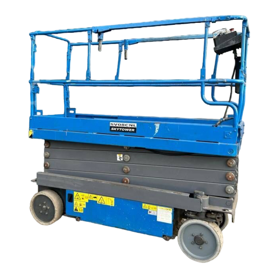
Page 18: Chapter 4 Part Name
Chapter 4 - Part Name Chapter 4 Part Name Part names M07ZO421 fig. f-1 (1) Manual Holder (15) Flash beacon (option) (2) Upper Control Panel (16) Extension Deck (3) Foot Switch (option) (17) Platform (4) Handle (18) Lift Cylinder (5) Lanyard Ancorage Point (19) Scissors Arm (6) Guardrails (20) Emergency Lowering Lever (7) Entry Gate (21) Pothole Protector (8) Battery Charger Cable (22) Chassis (9) Lower Control Panel (23) Step (10) Rear Wheel (24) Safety Prop (11) Serial Number Plate... -
Page 19: Upper Control Panel
Chapter 4 - Part Name Upper control panel (3) Overload warning light / Tilt light / System failure light Standard specifications • Overload warning light: When the platform is overloaded, this light blinks, the alarm buzzer sounds and all of the functions are disabled. • Tilt light: When the machine is on a slope, this light goes on, the alarm buzzer sounds and platform lift up function is disabled. • System failure light: This light goes on or blinks, in the event of a computer control system failure. (4) Horn switch Push the horn button and the alarm horn will sound. Release the horn button and the alarm horn will stop. Before moving the machine, sound the M084i120 horn to warn the personnel around the fig. f-f machine. -
Page 20: Optional Devices
Chapter 4 - Part Name Optional devices Lower control panel M084i300 fig. f-f (1) Battery charger indicator light (green) This light goes on when charging is finished. This light blinks when the battery M084i220 charger is charging batteries. fig. f-3 (2) Battery charger failure indicator light (red) (9) Steering dial (option) This light goes on or blinks, in the event of While the power indicator light battery charger failures. goes on by selecting the lift/ (3) Enable switch / Pre-start check switch travel select switch to "TRAVEL," • Hold this switch up, to turn the steering dial to right or operate the machine on the left and the steering wheels will ground. turn right or left. This operation is possible The enable switch is canceled if any of even when traveling. By returning the platform lift function is not operated more steering dial to neutral, the steering weels than 20 seconds after holding the enable will return to neutral automatically. - Page 21 Chapter 4 - Part Name (5) Emergency stop button Push down the emergency stop button to its "OFF" position to stop all functions. Pull up the emergency stop button to its "ON" position to operate the machine. (6) Overload warning light / Tilt light / System failure light • Overload warning light: When the platform is overloaded, this light blinks, the alarm buzzer sounds and all of the functions are disabled. • Tilt light: When the machine is on a slope, this light goes on, the alarm buzzer sounds and platform lift up function is disabled. • System failure light: This light goes on or blinks, in the event of a computer control system failure. (7) Key switch for Upper control / Off / Lower control selection Turn the key switch to the left and the upper controls will operate. Turn the key switch to center position and the machine will be off. Turn the key switch to the right and the lower controls will operate.
-
Page 22: Chapter 5 Workplace Check
Chapter 5 - Workplace Check Chapter 5 Workplace Check WARNING Do not move the machine to the workplace until the workplace check is performed. • Make sure to check the workplace before starting operation. Make sure there are no following hazards: – near electric power lines and apparatus – holes – sloped surfaces – slippery or icy surfaces – soft ground – bumps – curbs – debris – strong winds or gusts – other hazardous situations • Remove the hazards, if any, after the workplace check. If it is not possible to remove them, do not move the machine to the workplace. • The machine can be used only on level surfaces which are firm and for which all 4 wheels can maintain contact evenly with the ground. -
Page 23: Chapter 6 Pre-Start Check
Chapter 6 - Pre-Start Check Chapter 6 Pre‑Start Check Visual check WARNING Step 1 • Do not operate the machine before pre-start checks described in this Circle the machine once and check visually that there are no oil leaks, and no manual. damage to the decals or to the machine. • Perform the pre-start checks on a firm, level surface. Begin the checks with the Step 2 platform lowered, and the extension Make sure there is no damage, looseness, deck retracted. or missing parts in the wiring, bolts, each • If the pre-start checks reveal any switch and the guardrail. Make sure all the abnormalities, immediately put an guardrails are attached properly, and all “Out of Order” sign on the machine, the bolts, etc. are tightly fastened. and stop using the machine. The use of Step 3 the machine not repaired can cause a Make sure all decals are in place, legible serious accident. -
Page 24: Battery Level Check
Chapter 6 - Pre-Start Check Step 7 operates smoothly (no strange noises, vibrations, or rattling). After charging the battery, remove the (2) The platform lowering will stop when charging plug from the socket, and store the platform is 1.4 m (SV06CNL) / 1.6 m in the designated place. (SV08CNL) above the ground. To lower Battery level check the platform fully, check that there are no people and/or objects under the platform, Step 8 release the lift switch once, wait 2 seconds and then operate again to lower the Turn the key switch to “LOWER CONTROL." platform fully. Make sure the battery level indicator is in the green range. Emergency stop check Raising and lowering platform Step 13 check Push the emergency stop button. -
Page 25: Upper Control Check
(2) Hold the switch more than 0.3 second and the platform more. Make sure it does not then release it, the power indicator light raise at all (or go down naturally). goes on and the alarm buzzer sounds. (3) Raise and lower the platform completely Tilt warning check a few times, and make sure the platform Step 26 operates smoothly (no strange noises, vibrations, or rattling). (1) Lower and retract the platform fully. (4) The platform lowering will stop when (2) Remove the upper control panel from the the platform is 1.4 m (SV06CNL) / 1.6 m guardrails of the platform. (SV08CNL) above the ground. To lower (3) Place a piece of wood 40 mm thick under the platform fully, check that there are no both wheels on one side. people and/or objects under the platform, (4) Travel the machine up onto these pieces release the lift/travel joystick controller from the ground with the upper control once, wait 2 seconds and then operate panel. again to lower the platform fully. (5) Make sure that the tilt light goes on and Step 21 the alarm buzzer sounds. -
Page 26: Limited Travel Speed Check
Chapter 6 - Pre-Start Check Limited travel speed check Step 27 (1) Raise the platform about 2 m. Travel the machine forward or backward and make sure the machine travels at slow speed. (2) Some machines should not move at all unless the platform is lowered and the extension deck retracted. If this is the case, make sure the machine cannot travel when the platform is not in this state. 2211 Last check Step 28 Lower the platform fully and turn the key switch to "OFF." Step 29 Circle the machine and check visually that there are no oil leaks. -
Page 27: Chapter 7 Maintenance
– Always keep the charger dry. Periodic Maintenance • Perform a monthly and annual inspection referring to the separate service manual. – Depending on the laws of the country in which the machine is being used, keep M079E801 the records of the checks for the required fi g. ff1 number of years. – For any doubts you may have about Battery liquid level check handling, inspection or spare parts, • Check the battery liquid levels every day contact AICHI, AICHI's dealer, or the (especially when using the machine in authorized service shop nearest to you. warm and dry climates). – Refer to the separate service manual for • When the battery liquid level has dropped what must be checked regularly. more than 10 mm, add distilled water only. • If the machine has not been used for over The battery life will be shortened if anything one month, make sure to perform the other than distilled water is added. monthly inspection before use. • Keep the terminals and the upper surface of the battery clean. -
Page 28: Chapter 8 Operation
Chapter 8 - Operation Chapter 8 Operation Raising and Lowering Platform NOTICE (1) Hold the enable switch up. While the machine is being traveled, or (2) Operate the lift switch to "RAISE" or the platform is being raised or lowered, "LOWER." the motion alarm buzzer produces a (3) Immediately reduce the load if the overload warning light turned on when warning sound for personnel to stand raising the platform. away from the machine. NOTICE Lower Control (from ground) The lowering of the platform will stop when the platform is 1.f m (SV0fCNL) Enable Lift Emergency / 1.f m (SV0fCNL) above the ground. Switch Stop Button Switch To lower the platform fully, check that there are no people and/or objects under the platform, release the lift... -
Page 29: Raising And Lowering Platform
Chapter 8 - Operation Raising and Lowering Platform (2) Hold the switch more than 0.3 second and then release it, the power indicator light Lift / Travel Power Indicator goes on and the alarm buzzer sounds. Select Switch Light (3) Operate the lift/travel joystick controller to “FORWARD” or “BACKWARD” within 3 seconds after releasing the lift/travel select switch. NOTICE If the power indicator light goes off or blinks, release all function switches and then operate again from (1). Steering with Steering Switch (1) Select the lift/travel select switch to "TRAVEL." (2) Hold the switch more than 0.3 second and then release it, the power indicator light Lift / Travel Steering goes on and the alarm buzzer sounds. Joystick Switch M07X9620 (3) Operate the steering switch to “RIGHT”... -
Page 30: Extension Deck
Chapter 8 - Operation (4) By returning the steering dial to neutral, steering will return to neutral automatically. M079D200 fi g. fff Retracting (1) Get on the side of the platform that does not have the extension deck. Steering Dial M07X9A20 (2) Turn the handles, which are on the left fi g. fff and right guardrails, towards the inside until it stops. The lock of the extension Extension Deck deck will be released. (3) While holding the handles, pull the deck DANGER towards you until it stops. (4) Turn the handles to their original positions. Make sure the extension deck has The extension deck is now locked. extended or retracted fully and lock it, Fold Down Guardrail before operating the machine. -
Page 31: Raising Guardrails
Chapter 8 - Operation Raising Guardrails In order to put the guardrails back to the original position, perform the procedure backwards. DANGER Make sure the fold down guardrail has raised and lock it by pins, before M07X1000 operating the machine. The folding fi g. fff down guardrails which is not locked (4) Hold the areas B (see fig. 8-8) of the may move accidentally. Such an guardrails so that they do not fall down. accident increases the potential of fall Remove the lock pins A (see fig. 8-8), hazards. which lock the guardrails. CAUTION Take extreme care when getting on and off the platform after the guardrails have been folded down. M07X1100 fi g. fff (5) Keep holding the parts B, slowly push down the guardrails forward until the top rails rest on the middle rails (see fig. 8-9). CAUTION Do not hold guardrails except the areas B (see fig. f-f) when the guardrails fold down. Your hands might be pinched between the rails. -
Page 32: Chapter 9 Emergency Operation
Chapter 9 - Emergency Operation Chapter 9 Emergency Operation Emergency Lowering NOTICE If the platform has If the emergency operation was done been raised, and it is because of a malfunction, immediately not possible to lower stop the operation, and have the it because of power source failure, for example, a dead battery, machine checked and repaired. or because the upper stop switch has been Emergency Stop pressed, do the following: (1) The emergency lowering handle is located Use the emergency stop button. When at the front side of the machine (fig. 9-3, the emergency stop button is pressed and A). Pull the handle outward and lower the all of the functions are disabled. Press the platform. emergency stop button in the following cases: (1) When personnel on board the platform stops all of the machine movements to avoid danger. (2) When the personnel on the ground judges that the operation from the upper control is unsafe. -
Page 33: Chapter 10 Transporting
Chapter 10 - Transporting Method Chapter 10 Transporting • When loading/unloading, be sure to NOTICE have a guide assist you so that the wheels do not fall off the ramps and the • This information about transporting is transport vehicle bed. offered as a recommendation. • Failure to avoid these fall hazards could • Only the qualified persons shall use the result in death or serious injury. transport vehicle, crane, forklift, and the machine. Step 1 • All persons on transportation must Chock the wheels of the transport vehicle. comply with employer, work area, and (fig. 10–1, A) local and national safety regulations regarding the use of these machinery. • Each machinery must comply with all applicable regulations, and must be inspected and used in accordance with their manufacturer's instructions. Preparation before loading When transporting the machine by a transport vehicle, beware of the following. -
Page 34: Hoisting The Machine
Chapter 10 - Transporting Method Step 2 Attach the sling chains or wire ropes firmly, for example, with shackles, to all the hoisting rings. NOTICE If sling chains or wire ropes contact the platform, place pads on the platform to protect it. M081U801 Step 3 fi g. 10ff Place the sling wires or chains according Hoisting the machine to the fig. 10–3 and hoist the machine. Crane hook Lifting with forklift Protection is If a forklift is used, there are marks necessary on the machine. Adjust the 2 forklift forks to the marks and insert. Hoisting rings (4 rings) M084S120 fi g. 10f3 WARNING • Be sure the crane capacity, loading... -
Page 35: Chapter 11 Storage
Chapter 11 - Storage Chapter 11 Storage (1) Clean each part. (3) Grease each part. Apply enough rust-prevention oil to the cylinder rod of the steering cylinder. M0851501 M0851701 fi g. 11f1 fi g. 11f3 NOTICE (4) Disconnect the minus terminal (anode) of the battery. Cover the batteries, or remove them from the machine. Be careful about freezing in winter. (2) Wipe away dirt from around the electrical parts with a dry cloth. NOTICE Do not wash, particularly high-pressure washing, around the electrical parts. M0851801 fi g. 11ff NOTICE • When removing the battery, disconnect the minus terminal (anode) first. - Page 36 Chapter 11 - Storage (5) To prevent overdischarging, charge the battery every month. NOTICE The battery will self-discharge little by little even when it is not in use. If it is not charged for a long time, it will become over-discharged, and this will shorten the battery life. (6) In order to prevent rust when the machine is stored for a long time, operate the machine every month to prevent the loss of the oil layer on lubricated parts. M0851921 fi g. 11ff NOTICE Before operating the machine, wipe off the rustprevention oil that had been applied to the cylinder rod.
-
Page 37: Chapter 12 Specifications
AC motor power output (Travel) 0.7 kW (JIS) DC motor power output (Platform lift, Steering) 2.2 kW (JIS) Battery model GS Yuasa EB100 Battery capacity 200 Ah Battery voltage 12 V × 2 ( × 2 Parallel) Charging method Fixed current, fixed voltage Input voltage AC 100–240 V Charger Frequency 50 or 60 Hz Max. output current 25 A System voltage DC 24 V Rated hydraulic pressure 18.1 MPa (185 kg/cm Hydraulic oil tank capacity 5.3 L * These machine are intended for indoor use only. * The limit deviation tolerance without the instruction depends on AICHI's own standard. * Travel speed, function speed, and gradeability assume there is 1 person on the platform and the battery is fully charged. * Travel speed and gradeability are subject to surface conditions and sufficient traction. * Advisable atmospheric temperature range: -20℃ to +40℃... - Page 38 Chapter 12 - Specifications This page intentionally left blank.
Need help?
Do you have a question about the SV08CNL and is the answer not in the manual?
Questions and answers