Advertisement
Quick Links
EN
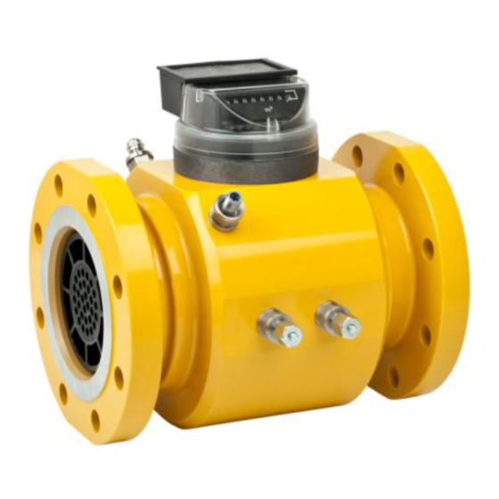
Turbine Gas Meter Type FMT-L / FMT-Lx / FMT-S / FMT-Q
If there remain any questions or remarks after reading these instructions,
WARNING
please contact the supplier of this product. Before installing the gas meter
the international, national, as well as local and company regulations related
to this product should be known.
A more extensive manual of this gas meter is available on request.
ENVIRONMENTAL CONDITIONS OF THE METER:
Mechanical class M2 & Electromagnetic class E1.
Operating temperature range from -40°C to +70°C.
Specific meter temperatures are shown on the typeplate
Only suitable for clean and dry gas
Meter can be installed in open air.
Avoid direct sunshine on the meter.
IP-classification of Index: IP67 when properly connected.
Electrical classification:
INSTRUCTIONS:
1)
Check the meter for damage due to transportation and handling. The turbine wheel
should rotate freely.
2)
Check the flow direction (arrow on body).
3)
Check the position of the meter (indication on name plate):
H:
horizontal only
V:
vertical only
H/V:
both horizontal and vertical
4)
The piping on the inlet side of the meter must be clean (free of dirt, welding beads and
pipe scale). For new installations it is recommended to install a wire mesh screen or
cone filter (250 micron) for the first four to six weeks of operation. Remove the
protective caps and / or plastic sheeting.
5)
Install the meter with a straight inlet section as shown in the picture 'Type of
Disturbances' further on in this manual. The inlet section must be made of straight pipe
with the same nominal diameter. The outlet section is at least 1xDN of the same
nominal diameter. For the FMT-Q the minimum straight inlet section is 5xDN. (Required
inlet sections are stated on the meter typeplate)
6)
The flow through the meter must be free of pulsations and the meter must be free of
vibrations in order to avoid measuring errors.
Installation and Operation Instructions
II 2 G T4
Advertisement

Related Manuals for FMG FMT-S


Summarization of Contents
General Warning and Safety Information
Regulatory Compliance and Supplier Contact
Ensure knowledge of regulations and contact supplier for questions before installation.
Sensor Assy Types and Introductions
Introduction to 3700 Reed Assy
Details the 3700 Reed Assy for FMG gas meters, providing pulse outputs and tamper status.
Introduction to 3710 MSR Assy
Describes the 3710 MSR Assy for FMG gas meters, offering pulse outputs and tamper status.
Introduction to 3720 Wiegand Assy
Explains the 3720 Wiegand Assy for FMG gas meters, providing pulse outputs and tamper status.
Intended Use in Explosive Atmospheres
Covers ATEX directive compliance for Assy use in explosive environments.
Electrical Specifications for Intrinsically Safe Sensors
3700/3710 Assy Intrinsically Safe Parameters
Details intrinsically safe input parameters for 3700/3710 sensor assemblies.
3720 Wiegand Assy Intrinsically Safe Parameters
Provides intrinsically safe input parameters for the 3720 Wiegand sensor assembly.
4000 HF Sensor Assy Details
Introduction to 4000 HF Sensor Assy
Introduces the optional 4000 HF Sensor Assy for FMG gas meters, detailing its pulse output capabilities.
Intended Use in Explosive Atmospheres
Confirms ATEX directive compliance for the 4000 HF Sensor Assy in explosive atmospheres.
UniEncoder Operation and Connection
UniEncoder Introduction
Overview of the UniEncoder type 04200xx-yyy for digital data transfer from gas meters.
UniEncoder Working Principles
Details the operation of the UniEncoder, including telegram transmission and power usage.
UniEncoder Connection Interface
Explains the connection requirements and pinout for the UniEncoder using binder connectors.
Need help?
Do you have a question about the FMT-S and is the answer not in the manual?
Questions and answers