Table of Contents
Advertisement
RM7897A1002, RM7897C1000
7800 SERIES
Relay Modules
APPLICATION
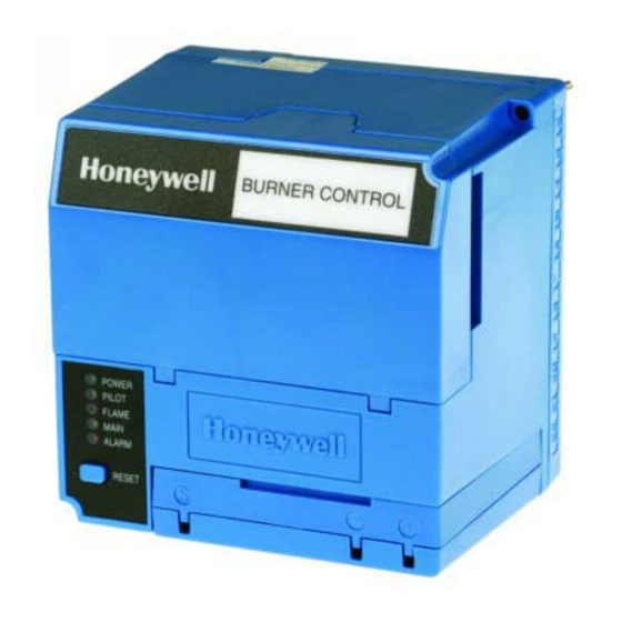
The RM7897A,C are microprocessor-based integrated burner
controls for automatically fired gas, oil, or combination fuel
single burner applications. The RM7897A,C system consist of
a relay module, subbase, amplifier, and purge card. Options
include keyboard display module (KDM), Personal Computer
Interface, Data ControlBus™ Module, remote display
mounting, Expanded Annunciator and Combustion System
Manager® Software.
Functions provided by the RM7897A,C include automatic
burner sequencing, flame supervision, system status
indication, system or self-diagnostics and troubleshooting.
The RM7897 adds a proof of closure input to the standard
primary control function of the RM7895/RM7896 product. It
adds a blinking fault code function to the POWER LED on
Alarm shutdown. It also adds programmable postpurge using
the S7800A1142 Keyboard Display Module (KDM). The
RM7897A1002 offers selectable pilot operation, intermittent
on terminal 8 or interrupted on terminal 21.
The RM7897C1000 offers interrupted pilot and delayed main
valve for 2-step firing (Low-High-Low) applications.
This document provides installation and static checkout
instructions. Other applicable publications are:
Publication
No.
63-2278
Q7700 Network Interface Unit Product Data
65-0084
Q7800A,B 22-Terminal Wiring Subbase
Product Data
65-0288
S7800A1142 Keyboard Display Module
Product Data
65-0091
S7810A Data ControlBus Module™ Product
Data
65-0095
S7820 Remote Reset Module Product Data
65-0097
221729C Dust Cover Installation
Instructions
65-0101
S7830 Expanded Annunciator Product Data
Product
INSTALLATION INSTRUCTIONS
Publication
No.
65-0102
ZM7850A Combustion System Manager™
Operating Instructions
65-0109
R7824, R7847, R7848, R7849, R7851,
R7861, R7886 Flame Amplifiers for the
7800 Series Product Data
65-0131
221818A Extension Cable Assembly
Product Data
65-0229
7800 SERIES Relay Modules Checkout and
Troubleshooting Product Data.
65-0092
QS7800A ControlBus™ Module, Standard
65-0227
QS7800B ControlBus™ Module, Multidrop
SPECIFICATIONS
Electrical Ratings (See Table 3):
Voltage and Frequency:
RM7897A,C: 120 Vac (+10/-15%), 50/60 Hz (± 10%).
Power Dissipation: 10W maximum.
Maximum Total Connected Load: 2000 VA.
Fusing Total Connected Load: 15A Fast Blow, type SC or
equivalent.
Environmental Ratings:
Ambient Temperature:
Operating: -40°F to 140°F (-40°C to +60°C).
Storage: -40°F to 150°F (-40°C to +66°C).
Humidity: 85% relative humidity continuous, noncondensing.
Vibration: 0.5G environment.
Approvals:
Underwriters Laboratories Inc. Listed: File No. MP268,
Guide No. MCCZ.
Canadian Standards Association Certified: Pending.
Factory Mutual Approved: Report No. Pending.
IRI Acceptable.
Federal Communications Commission: Part 15, Class B,
Emissions.
Product
66-1151
Advertisement
Table of Contents

Summarization of Contents
Specifications
Electrical Ratings
Electrical characteristics including voltage, frequency, power dissipation, and load ratings.
Environmental Ratings
Operating conditions for temperature, humidity, and vibration.
Approvals
Certifications and listings from various safety and regulatory organizations.
Installation
When Installing This Product
Key instructions and warnings to follow before and during installation.
Location
Guidelines for selecting a suitable installation location for the relay module.
Mounting Wiring Subbase
Instructions for securely mounting the wiring subbase.
Wiring Subbase Details
Internal Block Diagram
Illustrates the internal components and connections of the RM7897A,C.
Recommended Wire Routing
Guidelines for routing leadwires to prevent interference and ensure safety.
Static Checkout
Terminal Ratings
Details the electrical ratings for each terminal on the RM7897A,C.
Combinations for Terminals
Lists combinations for pilot fuel, main, ignition, and delayed main valves.
Testing Procedures
General Instructions
Steps for performing tests, including safety precautions and equipment.
Mounting RM7897A,C Relay Module
Instructions for securely mounting the relay module onto the subbase.
Static Checkout Table
Normal Operation and Abnormal Checks
Details normal operation and troubleshooting steps for each test case.
Setup of Post Purge
Explains the requirement for KDM for post purge timing setup.
Sequence Status LEDs
Exploded View of Relay Module
Diagram showing components of the RM7897A,C Relay Module.
Setup Screens
Screens for entering setup sub-routine and password.
Post Purge Setup
Setting Post Purge Time
Steps for setting the postpurge time using the KDM.
Confirming and Saving Settings
Procedures for confirming, saving, and releasing postpurge settings.
Principal Technical Features
Safety Shutdown (Lockout) Occurs If
Lists conditions that trigger a safety shutdown or lockout.
Sequence of Operation
Describes the operating sequences: Initiate, Standby, Prepurge, PFEP, MFEP, RUN, Post Purge.
Operation Details
Ignition Trials
Details the Pilot Flame Establishing Period (PFEP) and Main Flame Establishing Period (MFEP).
Run and Post Purge
Describes the RUN period and the Post Purge sequence.
Run/Test Switch
Explains the function of the Run/Test switch for sequence control.
Selectable Configuration Jumpers
Jumper Options and Effects
Details site-configurable jumper options and their impact on operation.
Troubleshooting
Guide to identifying and resolving faults using LED blinking codes.
Troubleshooting Fault Codes
Fault Codes and Recommended Troubleshooting
Lists fault codes and provides steps for recommended troubleshooting actions.
Further Troubleshooting and System Information
Additional Fault Codes
Details further fault codes and recommended troubleshooting steps.
Automation and Control Solutions
Contact information for Honeywell Automation and Control Solutions.


Need help?
Do you have a question about the RM7897C1000 and is the answer not in the manual?
Questions and answers