Table of Contents
Advertisement
Advertisement
Table of Contents

Summary of Contents for TEACH TECH King Lizard
- Page 1 From the Makers of TTR-892 10 + ASSEMBLY & INSTRUCTION MANUAL...
-
Page 2: Table Of Contents
C o n t e n t s I ntroduction P. 2 T ools Y ou May N eed P. 2 Mechanical Parts L ist P. 2 Plastic Parts P. 4 H ead Module Assembly P. 5 H ead Module T esting B ody Module Assembly P.17 B ody Module T esting... -
Page 3: I Ntroduction
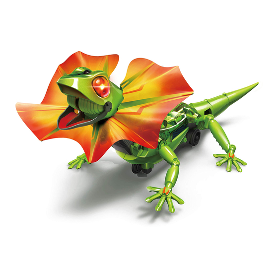
Introduction King Lizard is modeled after Australian Frilled Lizards. When these lizards are surprised or threatened they exhibit a pretty spectacular display. First it's the wide open, hissing mouth with sharp little canine teeth. Then comes the big reveal, the neck frills jump from limp to frightening in a snap. - Page 4 Round Shaft Round Shaft PC Board Motor With Connector Motor With Connector Black Black W / Long Wires W / Short Wires Battery Holder With Connector PC Board With Connector DC 6V Frill Adhesive Tape (Spare part : 1 pc) Sticker Spare Parts...
-
Page 5: Plastic Parts
Plastic Parts Cut the plastic parts when they are required. Spare Part Do not cut them in advance. 5 12 Spare Parts Tip:cut off the burrs before assembly burr burr burr... -
Page 6: H Ead Module Assembly
H e a d M o d u l e A s s e m b l y... - Page 7 P2 ( R ed) W / Short Wires ( S hort) 1: 1 B lack R ed S ide V iew...
- Page 8 Black Make sure “ “ is positioned as shown below. It is to assist you in assembling C8 correctly. B4x6...
- Page 10 Make sure adhesive tapes come with thin glued films while tearing off. Cut the frill as illustrated below. *Extra frill included...
- Page 11 T he opposite ( no color) N o stickers on the colored side. side should be facing up. F r o n t B a c k...
- Page 12 P u l l...
- Page 13 Note: Frill is not pictured below to clearly illustrate assembly.
- Page 14 P U S H...
- Page 15 B 10...
- Page 17 P u s h...
-
Page 18: B Ody Module Assembly
B o d y M o d u l e A s s e m b l y 1: 1 ( Y ellow) C2 2 C2 3 P10 ( L ong) ( Purple) D o not mix up C 4 & C3. U se C 4 for assembl y . - Page 19 P4 (White) W / Long Wires...
-
Page 20: B Ody Module T Esting
Make sure parts are locked firmly and snapped together where the markings are shown above. B o d y M o d u l e T e s t i n g... - Page 21 S et switch as shown, after around 8 seconds the part ( as illustrated) will keep rotating steadily . I f the part does not work or turns abnormally , go back to page 17, and re- do from step I mportant! C2 1 ( Middle)
- Page 22 Hammer lightly.
- Page 24 P7x2...
- Page 26 C2 0...
- Page 27 T op V iew Make sure that the wheels are not too tight or too loose. I mportant!
- Page 29 R ed B lack B 11 B 12...
- Page 30 P7x2 C2 4 C2 5 R ed B lack R ed B lack...
- Page 31 Side View...
- Page 34 F inished...
-
Page 35: S Tickers
S t i c k e r s... - Page 36 How To Play Neck adjustable angle...
-
Page 37: Escape Mode
Escape W hen the infrared ( I R ) sensor is activated in the mode Escape mode ( 1) , the K ing L iz ard will act shocked. T he frill will deploy , j aws gape and L ED ey es blaz e all before scurry ing away to a safe distance. -
Page 38: F Ollow- Me Mode
Follow-me W hen the I R sensor is activated in the F ollow- me mode mode ( 2 ) , y our K ing L iz ard will bluff the threat ( y ou) with an energetic frill display . I f y our K ing L iz ard does not sense danger it will follow y ou like a pet. -
Page 39: W Arning
W a r n i n g U se care when handling y o ur K ing L iz a rd R obot, any improper handling ( as shown below) might cause malfunction. - Page 41 NOTES:...
- Page 42 NOTES:...
- Page 43 NOTES:...
- Page 44 43500089231...


Need help?
Do you have a question about the King Lizard and is the answer not in the manual?
Questions and answers