Table of Contents
Advertisement
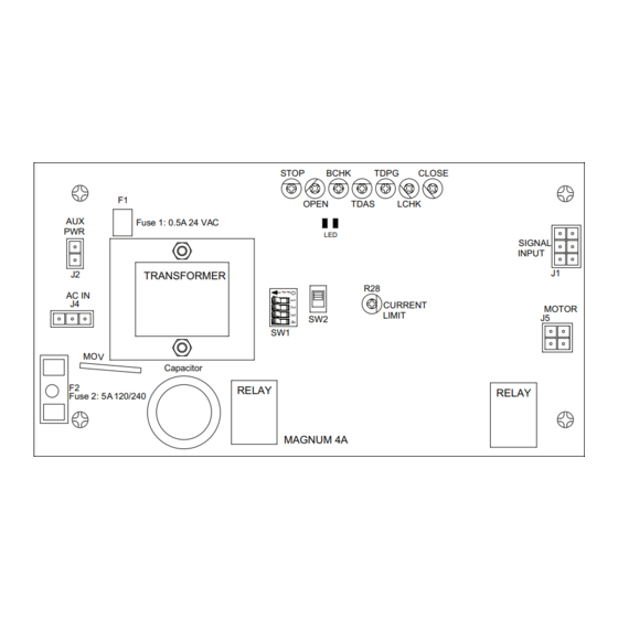
F1
AUX
Fuse 1: 0.5A 24 VAC
PWR
J2
TRANSFORMER
AC IN
J4
MOV
F2
Fuse 2: 5A 120/240
DN 0557
• Turn OFF all power to the Automatic Door if a Safety System is not working.
• Instruct the Owner to keep all power turned OFF until corrective action can be achieved by a NABCO
trained technician. Failure to follow these practices may result in serious consequences.
• NEVER leave a Door operating without all Safety detection systems operational.
Swing Door Operator
Wiring and Adjustment Manual
** with Magnum 4A Control*
SW1
Capacitor
RELAY
STOP
BCHK
TDPG
OPEN
TDAS
LED
R28
CURRENT
LIMIT
SW2
MAGNUM 4A
WARNING
S82 W18717 Gemini Drive
Muskego, Wisconsin 53150
Phone: (877) 622-2694
Fax: (888) 679-3319
www.nabcoentrances.com
Technical Support: (866) 622-8325
CLOSE
LCHK
RELAY
SIGNAL
INPUT
J1
MOTOR
J5
Part #C-00084
Rev. 9/09/16
Advertisement
Table of Contents

Related Manuals for Nabco GT-500


Summarization of Contents
CHAPTER 1: SCOPE
Section 1a. To the Installer
Details the installer's responsibilities for proper system installation and compliance with standards.
Section 1b. Objective
Outlines the intended installation locations and applications for the Opus Control system.
CHAPTER 2: GETTING STARTED
Section 2a. Features
Lists the key capabilities and functionalities of the Magnum 4A Control system.
Section 2b. Electrical Specifications
Provides technical electrical details and specifications for sensors and modules used with the system.
Section 2c. Output Power Guidelines
Guides on managing total current draw and using auxiliary power supplies for system accessories.
CHAPTER 3: MAGNUM 4A BOARD TERMINALS
Section 3a. Main Harness
Explains the wiring connections for the main harness, including the 6-pole terminal block and connectors.
Section 3b. Power Harness
Details the connections for the 120 VAC power input harness to the main control board.
Section 3c. Motor Harness (300/400/500)
Describes the motor harness connection for specific door operator models.
Section 3d. Motor Harness (710/8310/8710)
Describes the motor harness connection for specific door operator models.
Section 3e. Fuses
Explains the purpose and rating of fuses F1 and F2 within the control system.
CHAPTER 4: ADJUSTMENTS AND STATUS LEDS
Section 4a. Swing Door Positions
Illustrates and defines the key positions of a swing door during its operational cycle.
Section 4b. Adjustments
Covers the use of dip switches, slide switches, and potentiometers for system adjustments.
Section 4c. Status LEDs
Explains the function of the Green and Red LEDs for monitoring system status and safety signals.
CHAPTER 6: WIRING SAFETY DEVICES
Section 6a. Panic Breakout Latch/Switch (Open Loop Continuous Safety Circuit)
Details wiring for panic breakout switches on inswing units using an open loop safety circuit.
Section 6b. Panic Breakout Latch/Switch (Closed Loop Continuous Safety Circuit)
Explains wiring for panic breakout on units with a fail-safe circuit using a closed loop.
CHAPTER 7: WIRING DIAGRAMS (GENERAL)
Section 7a. GT-300-400-500 Single Door
Provides the general wiring diagram for a single door using GT-300/400/500 operators.
Section 7b. GT-300-400-500 (Simultaneous Pair)
Shows the wiring diagram for a simultaneous pair of GT-300/400/500 operators.
Section 7c. GT-300-400-500 (Simultaneous Pair w/One Magnum 4A Control)
Illustrates wiring for a dual-door setup with one Magnum 4A control.
Section 7d. GT-710-8310-8710 Single Door
Presents the wiring diagram for a single door using GT-710/8310/8710 operators.
Section 7e. GT-710-8310-8710 (Simultaneous Pair)
Shows the wiring diagram for a simultaneous pair of GT-710/8310/8710 operators.
Section 7f. GT-710-8310-8710 (Simultaneous Pair w/One Magnum 4A Control)
Details wiring for a dual-door setup with one Magnum 4A control on GT-710/8310/8710.
Section 7g. GT-1400 Single Fold with One Magnum 4A Control
Provides the wiring diagram for a single-fold GT-1400 door with one Magnum 4A control.
Section 7h. GT-1400 Bi-Fold with Two Magnum 4A Controls
Shows wiring for a bi-fold GT-1400 door using two Magnum 4A controls.
Section 7i. GT-1400 Bi-Fold with One Magnum 4A Control
Illustrates wiring for a bi-fold GT-1400 door with a single Magnum 4A control.
CHAPTER 8: WIRING DIAGRAMS (ACCESSORIES)
Section 8a. Transformer Installation and Wiring for 240 Volts
Details the installation and wiring procedures for a transformer powering the system.
Need help?
Do you have a question about the GT-500 and is the answer not in the manual?
Questions and answers