Advertisement
Table of Contents
- 1 Table of Contents
- 2 Special Features of Walinga Blowers
- 3 Section One
- 4 Lubrication
- 5 Maintenance-Retiming
- 6 Disassembly of Blower
- 7 Assembly of Blower
- 8 Assembly of Blower (Con't)
- 9 Section Three
- 10 Repair and Replacement
- 11 Timing Gear and Hub Removal
- 12 Bearing and Gear Replacement on Gear Head Units
- 13 Parts Description
- 14 Trouble Shooting
- 15 Blower Startup Checklist
- Download this manual
Advertisement
Table of Contents

Related Manuals for Walinga 614

Summary of Contents for Walinga 614
- Page 1 & M LOWER EPAIR AINTENANCE ANUAL HROME LOWERS MODELS: 510 & 614...
- Page 2 Blower Repair & Maintenance Manual #34-05198-6 v1.2 11.2014...
- Page 3 Dear Customer, Thank you for choosing WALINGA TRANSPORTATION EQUIPMENT. For your convenience, should you require any information related to Parts, Service or Technical Engineering, please contact one of the following Walinga Personnel in Guelph at 1-888 925-4642 unless noted* TECHNICAL - ENGINEERING: Tom Linde (ext 5) thl@walinga.com...
-
Page 4: Table Of Contents
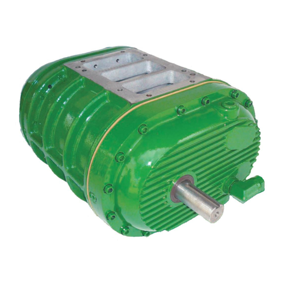
It is the purpose of this manual to help you properly install, maintain and service your WALINGA blower; follow the instructions carefully and you will be rewarded with long-life service. - Page 5 LONG LIFE DESIGN WALINGA Rotary Positive Displacement Blowers are designed to give the user the most compact unit possible. The drive shaft is extended for direct coupling or to accommodate a multiple V-belt drive. The following standard blowers are available from Walinga: WALINGA 510 &...
- Page 6 The standard shaft position on Walinga Super Chrome Blowers is at the left-hand side when viewed from the drive end. A right hand drive conversion is available to suit specific applications. Walinga or a trained dealer must be consulted prior to installation or perform this conversion to ensure that the warranty coverage is not voided.
-
Page 7: Special Features Of Walinga Blowers
These clearances are maintained by timing gears. Fig. 1 CONSTRUCTION Walinga blowers are ruggedly built for long life. Impellers are dynamically balanced to operate without vibration. Large alloy steel shafts are ground and polished. Bearings are heavy duty anti-friction type which enable the blower to maintain its original factory clearances. - Page 8 Both valves are supplied as standard equipment. Fig. 5 TIMING GEARS Walinga units are fitted with precision steel helical gears and the exclusive WALINGA TIMING HUB which enables the user to easily retime the unit in the field and has great shock absorbing qualities (Figure 6).
-
Page 9: Section One
Fill the housings until oil drips out of the oil level hole. Do not overfill. * Replace both plugs. Use Walinga Super Duty Blower Oil (Walinga Part# 98- 13813-5) In most cases, operating temperature of the blower will be in the 100-250 Deg. -
Page 10: Maintenance-Retiming
Aside from lubrication covered in Section One, the only maintenance procedure which may arise and needs explanation in the manual is the retiming of WALINGA blowers. Originally, the impellers are separated by pre-determined minute clearances which are designed into the unit. These clearances are maintained by the timing gears. - Page 11 DETERMINING PROPER IMPELLER CLEARANCE The timing of a blower is the setting of one impeller with respect to the other so they do not touch during operation. The clearances between the impellers are measured at points o-o and c-c when the impellers are in the positions shown in the Fig.
- Page 12 DETERMINING PROPER IMPELLER CLEARANCE (con’t) The following drawing illustrates how to check the minimum end clearances at the drive and gear end of the blower. The hammer is used to ensure that the play that is inherent in the spherical bearings is to the appropriate side and the clearance measurement is truly a minimum clearance measurement.
- Page 13 RESETTING IMPELLER CLEARANCES Refer to Figure 14 below. Impellers are held in time by gears which are bolted to a timing hub, which in turn is secured to the serrated impeller shaft by a lock nut. The timing gears can be rotated in relation to the hub by loosening the cap screws.
-
Page 14: Disassembly Of Blower
ASSEMBLY AND DISASSEMBLY OF BLOWER Fig 15 DISASSEMBLY OF BLOWER STEP PROCEDURE Drain oil from front and rear covers. (A) Unbolt covers by removing all exposed socket head cap screws. (B) Remove locknuts (C) lockwashers (D) from shaft on gear end of blower. Remove bolts (E) and washers (F) from timing gears, match the timing gears and lift them off of the hubs. -
Page 15: Assembly Of Blower
Disassembly of Blower (con’t) STEP PROCEDURE Remove retainer rings (I) from gear end bearing cartridges and remove bearings (P) from cartridges Remove seals (J) and O-rings (K) in cartridges. Mark position of headplate (L) to housing (M). Remove the two counter-sunk head capscrews and the two dowel pins from each headplate. -
Page 16: Assembly Of Blower (Con't)
ASSEMBLY OF BLOWER (con’t) STEP PROCEDURE Drive cartridge onto shafts with a driver, make sure the cartridges with the retainer rings are on the splined end of the shafts. At this time only the cartridges on the front of (drive end) the blower are to be bolted down using 5/16”... - Page 17 Assembly of Blower (con’t) STEP PROCEDURE Remove the locknuts and the pipe used in step 9 from the shaft and put the impellers in 45° position 88, top side of impeller touching bottom side of other impeller. In this position slide a 0.010” -0.012” feeler gauge between the impellers. Lay the timing hubs loose on the shafts so that the splines just start on the shaft splines.
-
Page 18: Section Three
SECTION THREE: REPAIR AND REPLACEMENT With proper maintenance and lubrication, normal life of bearings, gears and seals can be expected. To maintain the efficiency of your unit, however, these parts must be repaired or replaced when required. Fig. 16 TIMING GEAR AND HUB REMOVAL 1. - Page 19 GEAR END BEARING AND SEAL REPLACEMENT Fig. 17 1. Remove gear case (refer to Gear Case removal subsection). Check the fixed end impeller clearance. This clearance must be duplicated when repairs are completed. Remove the lock nuts and washers from the ends of both shafts and match mark the shafts, gears and hubs to assure repositioning during reassembly…...
-
Page 20: Bearing And Gear Replacement On Gear Head Units
BEARING AND GEAR REPLACEMENT ON GEAR HEAD UNITS Fig. 18 When excessive wear has spent the effectiveness of any one of the three bearings and/or two gears in gear head units, it is recommended that all five components be replaced to assure optimum performance and trouble-free service. - Page 21 Bearing and Gear Replacement on Gear Head Units (con’t) ASSEMBLY STEP PROCEDURE 1. Coat the input shaft and drive shaft with white lead. Oil all other components. 2. Replace the key on the input shaft. Press (or drive with a lead hammer) the gear into the input shaft until it is centered on the shaft step.
-
Page 22: Parts Description
94-00140-6 Lockwasher, W-06 94-00170-6 Dowel Pin 5/16 X 1 ¼ 94-00171-6 Timing Washer 510 .750 OD X .40 ID SK HD Cap Screw 5/16 – 18 – 1 Nyl 94-00176-6 SK HD Cap Screw 3/8 – 16 – 1 94-00179-6 SK HD Cap Screw 3/8 –... - Page 23 Blower Repair & Maintenance Manual #34-05198-6 v1.2 11.2014...
-
Page 24: Trouble Shooting
TROUBLE SHOOTING The function of trouble shooting is to locate quickly and to correct the cause of faulty operation and failure of equipment. No matter how well equipment is designed and manufactured, there may be times when faults will develop and failures will occur during operation. Whenever equipment fails to operate satisfactorily, the operator or repairman must be able to locate the cause and correct the trouble as quickly as possible. - Page 25 TROUBLE SHOOTING (con’t) Problem Possible Causes Solution Freezing-Headplate Misaligned V drive Align V drive overheating, excessive end clearance wear. Lack of Volume Clogged filter or muffler, incorrect Remove cause of obstruction installation of check valves Correct oil level – dirty oil – check for Excess bearing or gear Improper lubrications wear...
-
Page 26: Blower Startup Checklist
ROTARY POSITIVE BLOWERS INSTALLATION AND LUBRICATION BLOWER STARTUP CHECKLIST This start-up procedure should be follower during initial installation and after any shutdown period or after the blower has been worked on or moved to a new location. It is suggested that the steps be ... - Page 27 CAUTION - WHENEVER REMOUNTING BLOWER BE SURE THAT: Fig. 19 Belt Tensioning. Remove support lugs C (where supplied). Position blower on mounting plate, making sure that the Blower shaft and the midship shaft are and remain parallel. Tighten the eight blower mounting bolts properly. Lay the V-Belts loosely in the pulleys.
- Page 28 LOWER EPAIR AINTENANCE ANUAL HROME LOWERS MODELS: 510 & 614 CORPORATE HEAD OFFICE: 5656 Highway 6N RR#5, Guelph, Ontario,N1H 6J2 PHONE: (888) 925-4642 FAX: (519) 824-5651 AGRI-VAC MANUFACTURING FACILITY: 938 Glengarry Cres., Fergus, Ontario Canada N1M 2W7 Tel: (519) 787-8227 Fax: (519) 787-8210...
Need help?
Do you have a question about the 614 and is the answer not in the manual?
Questions and answers