Advertisement
Quick Links
I n stal l a ti o n and Mai n tenance of E1 ci r cui t s
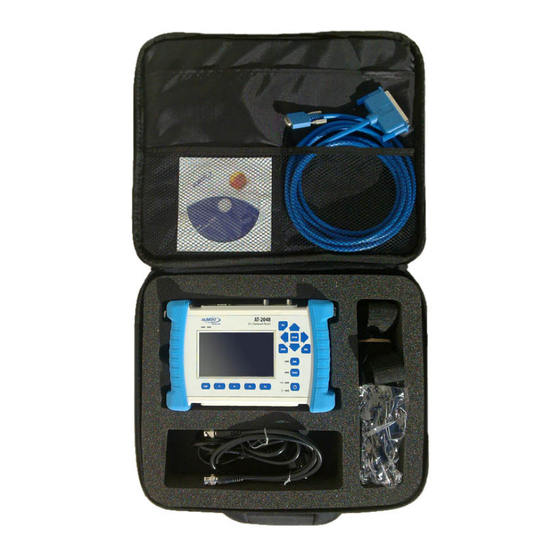
ALBEDO AT-2048 is a rug-
ged fully featured battery oper-
ated E1/Datacom handheld
tester designed in 2010 provid-
ing easy navigation and high
resolution screen. Low cost, fully
featured, it is a truly perfect field
tool for installation, acceptance
and maintenance of PDH and
Datacom links including bi-di-
rectional (BER) test functions.
A valuable tool that offers
generator, dual analyzer, USB,
Ethernet, and RJ45 interfaces. It
offers Jitter measurements and
pulse mask, therefore it can
monitor slots activity, delay and
frequency measurements fre-
quency measurements over
more than seven hours. Test re-
sults can be saved in a Memory
stick or transferred to a PC.
(C) ALBEDO TELECOM - 2010
Advertisement

Related Manuals for Albedo E1


Summary of Contents for Albedo E1
- Page 1 I n stal l a ti o n and Mai n tenance of E1 ci r cui t s ALBEDO AT-2048 is a rug- ged fully featured battery oper- ated E1/Datacom handheld tester designed in 2010 provid- ing easy navigation and high resolution screen.
-
Page 2: Installation And Maintenance Of E1 Circuits
The transmission medium consists of the links that connect distant nodes. • Nodes are those network elements that receive the signals and retransmit them further along until reaching the final users. Figure 1 ALBEDO AT.2048, E1, Datacom, Jitter, and Wander tester. - Page 3 E1 testing User Access Network Transmission Network Access Network User Terminal Terminal Node Node Network Nodes Transmission medium Source Coder Transmitter Receiver Decoder Sink message data coding line coding line decoding data decoding message Signals Information Information Figure 2 Elements of a telecommunications network. In other words, in a telecommunications network, user information is distributed as signals from one point to another through the transmission medium that connects the nodes in the system.
- Page 4 ALBEDO AT.2048 Transmitted signal Source Transmitter Attenuation Distortion Noise Received signal Receiver Sink Sampling times Data received Original data Figure 3 Effects of attenuation, distortion, and noise on transmission. 1.2 Transmission Medium The transmission medium can be defined as the environment where a signal is transmitted, be it material (electrical wires, optical fiber, open air, etc.) and nonma-...
- Page 5 E1 testing transmission and modify the original characteristics of the signals, which may end up being degraded by the time they reach their destination. The most significant impairments are attenuation, noise, and distortion. We look at these below in respect to a communications channel, which is defined as a means of unidirectional transmission of signals between two points.
- Page 6 ALBEDO AT.2048 Bandwidth Bandwidth H(f) H(f) Bandpass Lowpass Figure 5 The two basic transmission channels. In the frequency domain the channel transfer function H(f) determines the attenuation of each frequency and consequently the amplitude distortion. 1.2.2 Distortion Distortion produces a change in the original shape of the signal at the receiver end.
- Page 7 E1 testing Example: For a modem using 16 signal elements and a channel bandwidth (B) of 4,000 hertz (Hz), the maximum data transfer rate (C) is 32,000 bits per second (bit/s). 1.2.3 Noise Noise refers to any undesired and spurious signal that is added to an information signal.
-
Page 8: Channel Coding
ALBEDO AT.2048 Example: A typical value of S/N for a voice grade line is 30 dB (equivalent to a power ratio of 1,000:1). Thus for a bandwidth of 3,100 Hz the maximum data trans- fer rate (C) should be 30,894 bit/s. - Page 9 E1 testing • Direct current (dc) components should be avoided because they require physi- cal coupling of transmission elements. Since the earth/ground potential usually varies between remote communication ends, dc provokes unwanted earth-re- turn loops. • The use of alternating current (ac) signals permits a desirable physical isola- tion using condensers and transformers.
- Page 10 ALBEDO AT.2048 0 1 0 0 0 1 1 0 0 0 0 0 0 1 0 Non- Return to Zero Alternate Mark Inversion B8ZS Bipolar Eight-Zero Suppression HDB3 High Density B: balancing Bipolar V: violation Three Zeros Coded Mark...
- Page 11 E1 testing B8ZS HDB3 Number of ones Even Substitution Last pulse 000V –0V 000V Last ‘1’ polarity polarity – 000V – – 000V Figure 7 B8ZS and HDB3 coding. Bipolar violations are: a positive level and negative. “000V” or “B00V,” where “V” is a pulse that violates the AMI law of alternate po- larity, and B it is for balancing the polarity.
- Page 12 ALBEDO AT.2048 channels share a common transmission medium with the aim of reducing costs and complexity in the network. When the sharing is carried out with respect to a remote resource, such as a satellite, this is referred to as multiple access rather than multi- plexing.
- Page 13 E1 testing Sampling 0 0 1 0 1 1 0 11 Figure 9 Pulse code modulation (PCM) was the technology selected to digitalize the voice in telephone networks. Other pulse techniques are pulse amplitude modulation (PAM), pulse duration modulation (PDM), and pulse position modulation (PPM). which is why it is not generally used in indoor installations.
- Page 14 ALBEDO AT.2048 Analog Signal Sampling Sampling time Quantization Coding Figure 10 The three steps of digitalization of a signal: sampling of the signal, quantization of the amplitude, and binary encoding. The sampling theorem states that for digitalization without information loss, the...
- Page 15 E1 testing A telephone channel admits frequencies of between 300 Hz and 3,400 Hz. Because margins must be established in the channel, the bandwidth is set at 4 kHz. Then the ≥ ⋅ 2 4 000 8 000 sampling frequency must be ;...
-
Page 16: Frame Alignment
ALBEDO AT.2048 3.1 Basic Rates: T1 and E1 In 1965, a standard appeared in the U.S. that permitted the TDM multiplexing of 24 digital telephone channels of 64 kbit/s into a 1.544-Mbit/s signal with a format called T1 (see Figure 11). For the T1 signal, a synchronization bit is added to the 24 TDM time slots, in such a way that the aggregate transmission rate is: ×... - Page 17 E1 testing Time Slot 0 . . . Time Slot 16 . . . 1 0 1 1 S A S S Frame 0 125 μs S S S S 1 0 1 1 S S S S Submultiframe I 1 0 1 1 S S S S 1 0 1 1...
- Page 18 ALBEDO AT.2048 4.3.1 The CRC-4 procedure The aim of this system is to avoid loss of synchronization due to the coincidental appearance of the sequence “0011011” in a time slot other than the TS0 of a frame with FAS. To implement the CRC code in the transmission of 2-Mbit/s frames, a CRC-4 multiframe is built, made up of 16 frames.
-
Page 19: Monitoring Errors
E1 testing 4.3.3 Advantages of the CRC-4 method The CRC-4 method is mainly used to protect the communication against a wrong frame alignment word, and also to provide a certain degree of monitoring of the bit error rate (BER), when this has low values (around 10 ). - Page 20 ALBEDO AT.2048 the far end of the communication receives a 2Mbit/s frame and detects an erroneous block, it puts a “0” in the E-bit that corresponds to the block in the frame being sent along the return path to the transmitter (see Figure 15). This way, the near end of the...
- Page 21 E1 testing communication for the transmission and reception of frames. An alarm must be sent to the transmitter when a device detects either a power failure or a failure of the coder/decoder, in its multiplexer; or any of the following in its demultiplexer: loss of the signal (LOS), loss of frame alignment (LOF), or a BER greater than 10 1 0 1 1 Frame 0...
- Page 22 ALBEDO AT.2048 at in detail. CAS is defined in the ITU-T Rec. G.704, which defines the structure of the E1 frame. In CAS signaling, a signaling channel is associated with each information chan- nel (there is no common signaling channel), meaning that the signaling circuits are personalized for each channel.
- Page 23 E1 testing enough if we consider that the shortest signaling pulse (the one that corresponds to dialing the number) lasts for 100 ms. The alarm bit in the NMFAS is dealt with in a similar way to the NFAS. In this case, the alarms are transmitted between multiplex signaling devices connected to the 64-kbit/s circuits that correspond to signaling (TS16).
- Page 24 ALBEDO AT.2048 Table 2 2-Mbit/s events: Alarms, errors, and event indications. CAS-MRAI Channel associated signaling-multiframe remote alarm indication. Detected after two consecutive frames with the MRAI bit equal to 1 (ITU-T G.732). CAS-MAIS Channel associated signaling-multiframe alarm indication signal. It is detected if there are less than three zeros in the time slot 16 during two consecutive multi- frames.
- Page 25 E1 testing possible to identify the lower level frames inside a higher level frame. Recovering the tributary frames requires the signal to be fully demultiplexed. The higher hierarchical levels (8,448, 34,368, and 139,264 Mbit/s, etc.; referred to as 8, 34, and 140 Mbit/s for simplicity) are obtained by multiplexing four lower level frames within a frame whose nominal transmission rate is more than four times that of the lower level (see Table 3), in order to leave room for the permitted varia- tions in rate (justification bits), as well as the corresponding FAS, alarm, and spare...
- Page 26 ALBEDO AT.2048 8 Mbit/s : Group I 1 1 0 1 0 A S T : Group II : Group III : Group IV 42,4 μs 34 Mbit/s : Group I 1 1 0 1 0 A S T : Group II...
- Page 27 E1 testing 5.4 Multiplexing Level 4: 140 Mbit/s The structure of this frame is described in the ITU-T Rec. G.751 (see Figure 20). In this case, the frame is divided into six groups: • Group I contains the FAS, with sequence “111110100000;” the A-bit (remote alarm);...
- Page 28 ALBEDO AT.2048 The margins are set by the ITU-T recommendations for each hierarchical level. The signals thus formed are almost synchronous, except for differences within the permitted margins of tolerance, and for this reason they are called plesiochronous (see Figure 21).
- Page 29 E1 testing Alarm Management: Network Element Multiplexer A Multiplexer B Network Element RAI (bit A=1) AIS Formats: 2 Mbit/s 2Mbit/s CAS 8, 34, 140 Mbit/s RAI Formats: Time Slot 0 Time Slot 16 Frame 0 1 0 1 1 S S S S 1 0 1 1 S S S S Figure 22...
- Page 30 ALBEDO AT.2048 Several bits are used instead of just one, to provide protection against possible errors in transmission. On examining the control bits received, if they do not all have the same value, it is decided that they were sent with the majority value (a “1” if there are more 1s than 0s, for instance;...
- Page 31 E1 testing Selected Bibliography • William Stallings, Data and Computer Communications, Prentice Hall, 1997. • Fred Halsall, Data Communications, Computer Networks and OSI, Addison-Wesley, 1998. • Llorens Cerdá, Transmissió de Dades, Universitat Oberta de Catalunya, 1999. • Stanatios V. Kartalopoulos, Understanding SDH/SONET and ATM, IEEE Press, 1999. •...
- Page 32 ALBEDO Telecom A L B E D O T e l e co m d e s i g n s , m a n u f a ct u r e s , a n d d e l i v e r s so l u t i o n s t h a t e n a b l e...
Need help?
Do you have a question about the E1 and is the answer not in the manual?
Questions and answers