Table of Contents
Advertisement
Specifications
Power Source
Power Consumption
Average use
Standby condition
Display panel
Aspect Ratio
Visible screen size
Number of pixels
Sound
Speaker
Audio Output
Receiving Systems/Band name
Except B model
AC 220-240 V, 50 / 60 Hz
250 W (PX7B/E) (37-inch)
241 W (PV7F/P) (37-inch)
270 W (PX7B/E) (42-inch)
261 W (PV7F/P) (42-inch)
0.7 W (Without DVB recording)
20 W (With DVB recording)
16 : 9
94 cm (diagonal) (37-inch), 106 cm (diagonal) (42-inch)
819 mm (W) × 457 mm (H) (37-inch), 922 mm (W) × 518 mm (H) (42-inch)
737,280 (1,024 (W) × 720 (H)) [3,072 × 720 dots] (37-inch)
786,432 (1,024 (W) × 768 (H)) [3,072 × 768 dots] (42-inch)
160 mm × 42 mm × 2 pcs, 8 ohm
20 W [10 W + 10 W] (10 % THD)
PAL B, G, H, I, SECAM B, G, SECAM L / L'
VHF E2 - E12
VHF A - H (ITALY)
GPH10DE Chassis
VHF H1 - H2 (ITALY)
UHF E21 - E69
© 2007 Matsushita Electric Industrial Co., Ltd. All
rights
reserved.
distribution is a violation of law.
ORDER NO.PCZ0706054CE
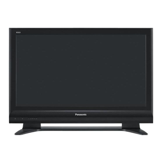
Plasma Television
Unauthorized
copying
and
Advertisement
Table of Contents

Related Manuals for Panasonic Viera TH-42PX7E


Summarization of Contents
Specifications
Power Consumption
Details power usage for Average use and Standby.
Display Panel
Aspect Ratio, Visible screen size, and Number of pixels.
Safety Precautions
General Guidelines
General rules for conducting repairs and servicing.
Touch-Current Check
Procedure for measuring leakage current on exposed metallic parts.
Service Information
Electrostatic Discharge (ESD) Prevention
Techniques to reduce component damage from static electricity.
Lead-Free Solder (PbF) Handling
Notes on handling lead-free solder, melting points, and precautions.
Service Procedures
Remove the Rear Cover
Instructions and diagram for removing the rear cover.
Plasma Panel Replacement
Step-by-step guide for replacing the plasma panel.
Diagnostics and Service Mode
Self-check Function
Using the self-check function to test the unit.
Power LED Blinking Timing
Chart correlating power LED blinks to defective blocks.
Service Mode Access
Steps to enter service mode via remote control.
Adjustments
Driver Set-up
Adjusting driver section voltages referring to panel data.
White Balance Adjustment
Procedure for adjusting PAL and HD panel white balance.
Internal Component Views
P-Board Conductor Views
Foil side view of the P-Board with component labels.
DG-Board Conductor Views
Foil side view of the DG-Board with component labels.
Schematics and Block Diagrams
Main Block Diagrams
Block diagrams illustrating the main functional units of the television.
P-Board Schematic Diagrams
Detailed circuit schematics for the P-Board.
DG-Board Schematic Diagrams
Detailed circuit schematics for the DG-Board.
Replacement Parts List
Exploded Views
Visual representation of parts for replacement.
Mechanical Replacement Parts List
List of mechanical parts with part numbers and descriptions.
Electrical Replacement Parts List (37inch)
List of electrical parts with part numbers and descriptions.
Need help?
Do you have a question about the Viera TH-42PX7E and is the answer not in the manual?
Questions and answers