Advertisement
Table of Contents
Commissioning, operation,
and maintenance: GOLD 1-3
1. INTRODUCTION
1.1 GENERAL
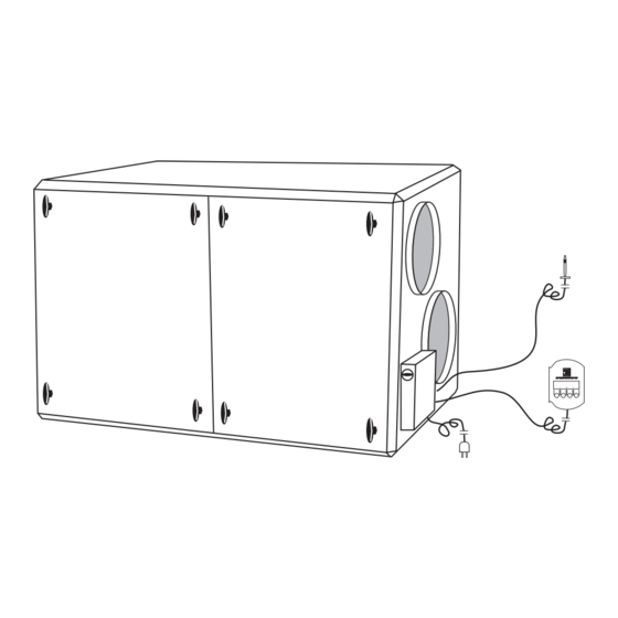
GOLD is a complete air handling unit, with built-in control
system, developed and manufactured by PM-LUFT AB.
The unit contains supply and exhaust air fans, rotary heat
exchanger Turbo, supply and exhaust air filters F85/EU7
and control system.
These instructions are for the commissioning, operation,
and maintenance of the unit. It is important that they are
read by all personnel involved before the unit is put into
service. Please see separate instructions for installation
WARNING!
Inspection hatches located on the pressure side behind
the fan must not be opened while the fan is operating. The
hatch can open suddenly and cause personal injury.
Right to make modifications without prior notice
INDEX
1.
INTRODUCTION ............................................................ 1
2.
ELECTRICAL CONNECTION ........................................ 4
3.
CONNECTION OF EXTERNAL FUNCTIONS ............... 5
4.
WIRING DIAGRAM POWER CARD .............................. 6
5.
WIRING DIAGRAM CONTROL CARD .......................... 7
6.
STARTING-UP ............................................................... 8
7.
ADJUSTMENTS ............................................................. 9
8.
FUNCTIONS ................................................................. 13
9.
ADJUSTMENT PROTOCOLE ...................................... 18
10. ALARM ......................................................................... 19
11. MAINTENANCE ............................................................ 21
TELEPHONE NUMBERS PM-LUFT ............................ 22
GOLD 1-3 SK-GB -708
:
::
:
1
Advertisement
Table of Contents

Related Manuals for PM-LUFT GOLD 3


Summary of Contents for PM-LUFT GOLD 3
-
Page 1: Table Of Contents
INTRODUCTION ............1 GOLD is a complete air handling unit, with built-in control ELECTRICAL CONNECTION ........4 system, developed and manufactured by PM-LUFT AB. CONNECTION OF EXTERNAL FUNCTIONS ....5 The unit contains supply and exhaust air fans, rotary heat WIRING DIAGRAM POWER CARD ...... - Page 2 GOLD 1-3 SK-GB-708 1.2 SPECIFICATION When contacting PM-LUFT, please use manufacture number, program version (see 7.3), and description as given below: Air Handling System GOLD-a-b-cc Silencer GODA-1-aaa Size 025, 031, 040 Type Round, Size 016-040 Size Silencer GODB-1-aaa 2, 3...
- Page 3 GOLD 1-3 SK-GB -708 GOLD size 1 Drive motor heat exchanger Throttle damper Drive belt Locking heat exchanger Exhaust air filter knobs fan Locking knob Supply air sensor flex. conn. (to be placed in supply air duct) Exhaust air fan...
-
Page 4: Electrical Connection
GOLD 1-3 SK-GB-708 2. ELECTRICAL CONNECTION 2.1 Power Units in sizes 1 and 2 are connected with factory installed electrical plug, otherwise permanently connected to single phase 230V, 50Hz, 10A. For size 3 permanent connection applies, 2 x 230 V + N, 50 Hz, 2 x 10 A. -
Page 5: Connection Of External Functions
GOLD 1-3 SK-GB -708 3. CONNECTION OF EXTERNAL FUNCTIONS 3.6 Flow indication Supply–Exhaust air On connections 9(+) and 10(-) there is a output voltage of 3.1 General 0 –10 VDC which is proportional to measured supply air Cables from external functions are connected to flow. -
Page 6: Wiring Diagram Power Card
EXHAUST AIR SENSOR HEAT EXCH EXHAUST AIR MOTOR FAN SUPPLY AND CONTROL OUTDOOR AIR SENSOR Blue Brown Black Yell/Green FUSE Blue SUPPLY AND GOLD POWER Brown CONTROLLING White SUPPLY AIR FAN Yellow Green PRESSURE SENSOR SA–FLÄKT GOLD-PRESSURE Black PRESSURE Yell/Green SENSOR Blue EA–FLÄKT... -
Page 7: Wiring Diagram Control Card
GOLD 1-3 SK-GB -708 5. WIRING DIAGRAM CONTROL CARD Size 1 and 2 DISPLAY Folio MAIN SWITCH *GOLD* CONTROL CARD SUPPLY AIR Black SENSOR Brown Blue CONNECTION Blue Brown POSSIBLE White HEATER Yellow Green GOLD-CPU Green Yellow White Brown GOLD-PROG... -
Page 8: Starting-Up
GOLD 1-3 SK-GB-708 6. STARTING-UP When the unit is connected and the main switch is connected for the first time, a language selection menu 1 = SVENSKA is shown on the display. 2 = ENGLISH Choose desired language by pushing the button for respective number. -
Page 9: Adjustments
GOLD 1-3 SK-GB -708 *GOLD* DAY 1 – 10:15 HIGH SPEED AUTO OPER STOP S-CL PROG ACTUAL TIME *GOLD* DAY 1 – 10:15 DAY 1 – 10:15 PV 02:2 : OPER 0250D SETTING PROG TEMP FLOW FUNC HIGH SPEED 00.00–00.00... - Page 10 GOLD 1-3 SK-GB-708 7.2 Switching clock ACTUAL TIME First programme the right day and time. DAY 1 10:15 Then programme desired times for High speed operation. PROG Then program desired times for High speed operation. DAY on second line can be chosen 0, 1, 2, 3, 4 , 5, 6, 7, 1–5, 1–7.
- Page 11 GOLD 1-3 SK-GB -708 7.4 Temperatures ERS-REG STEP 2 ° 7.4.1 ERS regulation OFF/ON-DIFF ° BREAK POINT Exhaust air temperature Related Supply air regulation PROG (ERS). This means that the supply air temperature is regulated in relation to the exhaust air temperature.
- Page 12 GOLD 1-3 SK-GB-708 7.5. Flows HIGH SPEED LOW SPEED Where the flows are programmed in l/s and the smallest 700 l/s 400 l/s step is10 l/s. 700 l/s 400 l/s PROG Min and max flows: Size Max flow l/s Min flow l/s...
-
Page 13: Functions
GOLD 1-3 SK-GB -708 8. FUNCTIONS 8.1 General Following functions can be altered in the display. Summer night cooling (0/1) Outdoor air temp compensation (0/1) Set value displacement (0/1) Cooling unit on/off (0/1) Cooling unit 0–10 VDC Duct calibration (0/1) Service period (0–9999 months) - Page 14 GOLD 1-3 SK-GB-708 8.4 Set value displacement At SET VALUE DISPL = 1 (on). The temperature set value can be displaced +/- 5°C with the help of 0–10 VDC external control. The set value displaced is the EA/SA-differance at ERS-...
- Page 15 GOLD 1-3 SK-GB -708 8.5.2 Stepless Regulation of Cooling At COOL AGGREGATE = 2, a control signal of 0 - 10V DC is maintained on plinth 11 (+) and 12 (-) for regulation of stepless cooling. (See 3.8.2) A neutral zone of 2° C. is allowed, as above.
- Page 16 GOLD 1-3 SK-GB-708 8.8 External high speed (time delay) EXT HS TIME DELAY 1:15 The function gives time delayed reset to low speed when CLOSURE = HIGH SPEED the input for external alteration between High speed and TIME FILTER TEST 22:59 Low speed shifts.
- Page 17 GOLD 1-3 SK-GB -708 8.13 Language selection 1 = SVENSKA The language can be altered between SVENSKA and 2 = ENGLISH ENGLISH at any time. The alteration is carried out when return to "main menu" PROG is done. Cooling recovery function...
-
Page 18: Adjustment Protocole
GOLD 1-3 SK-GB-708 9. Adjustment protocole Switching clock, actual time set Program version ......Times for high speed No 1 .... – ....DAY ..No 5 .... – ....DAY ..No 9 .... – ....DAY ..No 2 .... – ....DAY .. -
Page 19: Alarm
SUPP AIR MOTOR RELEASED All alarm texts are described below. Cause and some check points are given. If the error still remains, contact PM-LUFT . The alarms are not activated in programming menues. Resetting of alarm: – Manual reset means, if not anything else is said, that the button RES on the display is pushed. - Page 20 GOLD 1-3 SK-GB-708 The head processor can not communicate with the I/O *** ALARM 17 *** processor on the control card. "SA-FLOW BELOW SET VALUE" –Check that the processors are placed correctly in the *** ALARM 18 *** sockets. Automatic reset when the error is repaired.
-
Page 21: Maintenance
GOLD 1-3 SK-GB -708 *** ALARM 30 *** Electrically: The contact of the heat exchanger motor is disconnected. "COMMUNICATIONEN TO CONTROL CARD The screws in the rubber A/V:s are loosened and then the BROKEN" motor is removed. The unit has stopped. -
Page 22: Telephone Numbers Pm-Luft
POLAND: Poznan 061-47 71 43 GREAT BRITAIN: London 01440-71 46 99 HUNGARY: Budapest 36-1-157 10 75 Head office and manufactory: PM-LUFT AB, Box 300, 535 23 KVÄNUM. Tel 0512-32 200, fax 32 300. Right to make modifications without prior notice...
Need help?
Do you have a question about the GOLD 3 and is the answer not in the manual?
Questions and answers