Table of Contents
Advertisement
Advertisement
Table of Contents

Related Manuals for Balluff BIS V-6108 PROFINET


Summary of Contents for Balluff BIS V-6108 PROFINET
- Page 1 BIS V-6108 PROFINET Technical Reference, Operating Manual english...
- Page 2 www.balluff.com...
-
Page 3: Table Of Contents
Processor Unit Scope of Delivery Processor Unit Installation Electrical Connections Technical Data Startup Configuration Parameter Configuration Integration into Project Planning Software Device Functions Function Principle of the BIS V-6108 Process Data Buffer Function Indicator Examples Display Webserver Appendix Index www.balluff.com english... -
Page 4: User Instructions
BIS V-6108 PROFINET Processor Unit User Instructions 1.1 About This This manual describes the processor unit for BIS V-6108 Identification Systems and startup Manual instructions for immediate operation. 1.2 Typographical The following conventions are used in this manual: Conventions Actions Action instructions are indicated by a preceding triangle. The result of an action is indicated by an arrow. -
Page 5: Abbreviations
BIS V-6108 PROFINET Processor Unit User Instructions 1.5 Abbreviations Balluff Identification System Code Present Cyclic Redundancy Check Discovery and basic Configuration Protocol Device ID Decentralized peripherals EEPROM Electrical Erasable and Programmable ROM EIRP Equivalent Isotropically Radiated Power Electromagnetic compatibility Effective Radiated Power... -
Page 6: Safety
– Components are used that are not part of the BIS V Identification System, – Components are used that have not been explicitly approved by Balluff. Operation and testing The operator is responsible for ensuring that local safety regulations are observed. -
Page 7: Basic Knowledge
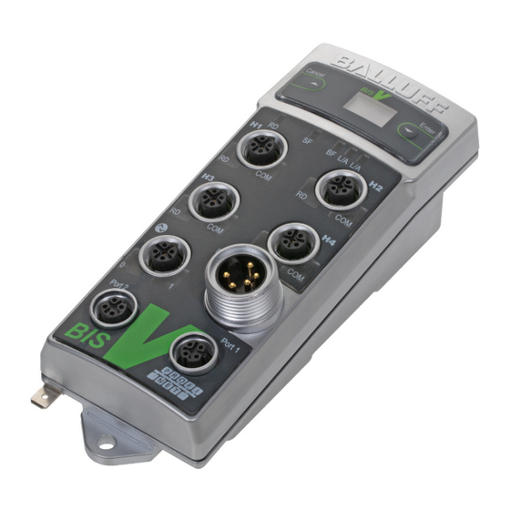
Power for the data carrier provided by the read/write heads via carrier signal – USB Port – 2 × PROFINET IO port – Display with keys for startup and configuration – Control displays – Webserver for diagnostics and service functions www.balluff.com english... -
Page 8: Control Function
BIS V-6108 PROFINET Processor Unit Basic Knowledge 3.3 Control Function The processor unit is the link between data carrier and host control system. It manages two-way data transfer between data carrier and R/W head and provides buffer storage. The processor unit uses the R/W head to write data from the host control system to the data carrier or reads the data from the carrier and makes it available to the host control system. -
Page 9: Profinet
Processor Unit Basic Knowledge 3.5 Read/Write For BIS V-6108-048-C002, read/write heads in the BIS VM-3 _ _, BIS VL-3 _ _, and Heads H1…H4 BIS VU-3 _ _ series can be connected to terminals H1...H4. BIS V-6108-048-C102 also supports read/write heads in the BIS C-3 _ _ series (Adapter required). -
Page 10: Io-Link
The communication driver can be installed as needed, but is not required for the USB port and BIS V to function. Note Visit www.balluff.com for more information on available software and accessories. english... -
Page 11: Installation
– 5 × closure cap – Safety Precautions Note Visit www.balluff.com for more information on available software and accessories. 4.2 Processor Unit Installation Figure 2: Mechanical connection (dimensions in mm) Figure 3: Installation examples (A: attachment to DIN rails, B: attachment to T-slotted framing) -
Page 12: Electrical Connections
BIS V-6108 PROFINET Processor Unit Installation 4.3 Electrical Note Connections Make the ground connection either directly or using an RC combination to ground. Connections H1…H4 Read/Write Heads Service/IO-Link USB function Service / Power Service/IO-Link IO-Link (master function) Port 1 PROFINET IO port 1 Port 2 Port 1 Port 2... -
Page 13: Technical Data
Ripple ≤ 10% Power Consumption ≤ 2 A Application interfaces PROFINET IO, IO-Link Application IO-Link port M12, A-coded, female interfaces Pin 1 +24 V DC, 1 A Pin 2 USB+ Pin 3 Pin 4 IO-Link / input max. 500 mA Pin 5 USB– www.balluff.com english... - Page 14 BIS V-6108 PROFINET Processor Unit Technical Data Operating Ambient Temperature 0 °C…+60 °C conditions Storage Temperature 0 °C…+60 °C EMC (BIS V-6108-048-C002) – EN 61000-6-2 – EN 61000-4-2/4/5/6 – Severity level 2B/3A/2A/3A – EN 61000-4-3 80 MHz – 1000 MHz – Severity level 3A 1400 MHz –...
-
Page 15: Startup
"bisv6108048". Display setting/ The device can be restored to factory condition using the display. Details for resetting and on menu navigation menu guidance of the display are described in Chapter “Display” on page www.balluff.com english... -
Page 16: Configuration
BIS V-6108 PROFINET Processor Unit Startup 6.1 Configuration In project planning for PROFINET devices, a device is mapped as a modular system that consists of a "BIS V-6108" header module and multiple data modules. GSDML file The device data required for project planning is stored in GSDML files (General Station Description). - Page 17 IOL_I_32byte 32 Byte Data modules for IO-Link_outputs Data module Data width IOL_O_1byte 1 byte IOL_O_2byte 2 bytes IOL_O_4byte 4 Byte IOL_O_6byte 6 Byte IOL_O_8byte 8 Byte IOL_O_10byte 10 Byte IOL_O_16byte 16 Byte IOL_O_24byte 24 Byte IOL_O_32byte 32 Byte www.balluff.com english...
- Page 18 BIS V-6108 PROFINET Processor Unit Startup Coding IO-Link Data modules for IO-Link_inputs_outputs Data Modules Data width Data module Input Output IOL_I/O_1/_1byte 1 byte 1 byte IOL_I/O_2/_2byte 2 bytes 2 bytes IOL_I/O_2/_4byte 2 bytes 4 Byte IOL_I/O_4/_4byte 4 Byte 4 Byte IOL_I/O_4/_2byte 4 Byte 2 bytes...
- Page 19 All data carriers in the series used (e.g. BIS VM) are recognized* Mifare ISO 15693 EM4x02 Hitag1 HitagS BIS C 32 byte BIS C 64 byte 16 bits Process data length 8…254 Fixed module * Not for read/write heads BIS VU-_ _ www.balluff.com english...
- Page 20 BIS V-6108 PROFINET Processor Unit Startup IO-Link port Slot 5, subslot 1 parameter Index Byte Bit Length Contents Values Default 6 bits Cycle time 0…63 2 bits Cycle time base 0/1/2 1 byte Data window offset 0…31 1 byte Max. data input length 0…32 2 bits Validation type...
-
Page 21: Parameter Configuration
IO-Link safe state This function is an extension of the IO-Link port starting configuration. A safe state that the port is to take on in the case of a loss of bus communication can be predefined for the port. www.balluff.com english... - Page 22 The following data carriers are available for the BIS V-6108 processor unit. Note The data carriers contain additional memory ranges for configuration and protected data. These ranges cannot be processed using the BIS V-6108 processor unit. Mifare data carriers (for read/write heads BIS VM): Balluff data carrier Manufacturer Description Memory Memory...
- Page 23 To achieve the read times during dynamic operation that are specified on page 71 the Tag Type parameter must be set to "BIS C 32 Byte" or "BIS C 64 Byte" on the respective head. For read/write heads BIS VU: Balluff data carrier type Manufacturer Memory capacity BIS U-1_ _ Balluff...
- Page 24 BIS V-6108 PROFINET Processor Unit Startup CRC check The number of usable bytes thus decreases when using the checksum. Balluff data carrier type Memory capacity Usable bytes for CRC_16 BIS M-1_ _-01 752 Byte 658 Byte BIS M-1_ _-02 2000 Byte...
- Page 25 Information about configuring the transmission power for BIS VU read/write heads can be found in the manual for the BIS L read/write head. Manuals are available at www.balluff.com. LEDs off This parameter switches off the LEDs on the respective read/write head. This function is configured in the respective read/write head module (only BIS VM and BIS VU).
- Page 26 BIS V-6108 PROFINET Processor Unit Startup UID Compare This parameter indicates how often the 5-byte ID of a BIS L-1_ _-03 data carrier is imported and Count compared before the data carrier is shown as identified. The value default setting is 2. For highly dynamic applications, this value can be set to 1 (only BIS VL).
- Page 27 ⇒ A message appears once the process has finished. ► Confirm the message and close the window. ► Select the menu command "Tools | Update catalog". ⇒ The devices are displayed in the product tree. Figure 6: Parameter configuration with a GSDML file www.balluff.com english...
- Page 28 Adding a DP The devices are located in the hardware catalog under "Other field devices", "Ident systems", slave "Balluff", "RFID". The module is added as PROFINET IO. ► Select the PROFINET rail. ► Double-clicking adds the device as a PROFINET IO.
- Page 29 The quantity of process data (buffer size) for a read/write head can be selected by deleting and write heads plugging in a corresponding "head" module (min. 8 bytes, max. 254 bytes). When a module is not plugged in, no process data is configured. Figure 10: Configuring read/write heads www.balluff.com english...
- Page 30 BIS V-6108 PROFINET Processor Unit Startup Configuring the If a IO-Link module is to be installed, the standard I/O module has to be deleted first. IO-Link module ► Select the corresponding IO-Link module after the deletion. Figure 11: Selecting the IO-Link module ►...
-
Page 31: Device Functions
Figure 13: Example for a total buffer size of 80 bytes (4 × 16 bytes: heads H1 to H4, 16 bytes: IO-Link) R/W head 1 R/W head 4 R/W head 2 IO-Link R/W head 3 Subsequently, potential additional ranges for IO-Link. IO-Link IO-Link data is transmitted unchanged to the IO-Link Slaves via the IO-Link Master. IO-Link buffer: 0…32 bytes (max.) www.balluff.com english... -
Page 32: Process Data Buffer
BIS V-6108 PROFINET Processor Unit Device Functions 7.2 Process Data Buffer Output buffer The control commands for the identification system and the data to be written to the data carrier are transmitted via the output buffer. Bit No. Subaddress = Bit Header Command Identifier Data... - Page 33 Transmission of data that was read from the data carrier. Last byte 2nd Bit Header If the 1st and 2nd bit headers match, the data is valid. Note Displaying the "multiple tag function" (MT) is not possible with BIS C read/write heads. www.balluff.com english...
- Page 34 BIS V-6108 PROFINET Processor Unit Device Functions Input buffer Status codes Status code Description of Function Everything OK. Job cannot be run because there is no data carrier in range of the read/write head. Cannot read the data carrier. Data carrier was removed from the R/W head's range during reading. Cannot write to the data carrier.
- Page 35 2nd Bit Header If the 1st and 2nd bit headers match, the data is valid. Depending on the number of bytes to read and the configured buffer size, multiple bus cycles may be necessary to transfer the data. www.balluff.com english...
- Page 36 BIS V-6108 PROFINET Processor Unit Device Functions Structure of the Command Identifier 81 : Read Data Carrier with 24-bit Addresses commands for read/write heads When assigning addresses to data carriers with expanded memory, the start address and number of bytes can be specified as 24-bit values. Information about executing the command as well as about return values are drawn from the 01 command (See “Command Identifier 00...
- Page 37 Subaddress Meaning Description of Function 1st Bit Header Data Provides information on the status of a query. … Data No meaning Last byte 2nd Bit Header If the 1st and 2nd bit headers match, the data is valid. www.balluff.com english...
- Page 38 BIS V-6108 PROFINET Processor Unit Device Functions Structure of the Command designator 82 : Write to data carrier with 24-bit addresses commands for read/write heads When assigning addresses to data carriers with expanded memory, the start address and number of bytes can be specified as 24-bit values. Information about executing the command as well as about return values are drawn from the 02 command (See “Command Identifier 02...
- Page 39 Address for the "Auto Read" function starting from which byte) the data carrier is read. The value is stored in the EEPROM. … None No meaning Last byte 2nd Bit Header Valid data is present if the 1st and 2nd bit strings match. www.balluff.com english...
- Page 40 BIS V-6108 PROFINET Processor Unit Device Functions Structure of the Command designator 09 : Type and serial number commands for read/write heads If a data carrier is recognized in the active read/write zone of the read/write head, this command will return the read-write head type as well as the data carrier type and serial number of the detected data carrier.
- Page 41 Meaning Description of Function 1st Bit Header Status code Provides information on the status of a query. … None No meaning Last byte 2nd Bit Header If the 1st and 2nd bit headers match, the data is valid. www.balluff.com english...
- Page 42 BIS V-6108 PROFINET Processor Unit Device Functions Structure of the Command Identifier 91 : Copy Data Between Data Carriers with 24-bit Addresses commands for read/write heads When assigning addresses to data carriers with expanded memory, the start address and number of bytes can be specified as 24-bit values. Information about executing the command as well as about return values are drawn from the 11 command (See “Command designator...
- Page 43 Meaning Description of Function 1st Bit Header Status code Provides information on the status of a query. … None No meaning Last byte 2nd Bit Header If the 1st and 2nd bit headers match, the data is valid. www.balluff.com english...
- Page 44 BIS V-6108 PROFINET Processor Unit Device Functions Structure of the Command Identifier 92 : Initialize CRC_16 Data Check with 24-bit Addresses commands for read/write heads When assigning addresses to data carriers with expanded memory, the start address and number of bytes can be specified as 24-bit values. Information about executing the command as well as about return values are drawn from the 12 command (See “Command designator...
- Page 45 Description of Function 1st Bit Header Data Value that is to be written to the data carrier. … None No meaning Last byte 2nd Bit Header If the 1st and 2nd bit headers match, the data is valid. www.balluff.com english...
- Page 46 BIS V-6108 PROFINET Processor Unit Device Functions Structure of the Command Identifier B2 : Write Constant Value to Data Carrier with 24-bit Addresses commands for read/write heads When assigning addresses to data carriers with expanded memory, the start address and number of bytes can be specified as 24-bit values.
- Page 47 Details and more information about the available parameters as well as BIS VU-specific commands can be found in the manual of the BIS VU read/write head BIS VU read/write used (Available at www.balluff.com). heads Command Identifier 40 : Select (Select Data Carrier in Multi-tag Mode) In the Multi-tag Mode, the Select command selects a single data carrier from within a data carrier population.
- Page 48 BIS V-6108 PROFINET Processor Unit Device Functions Specific Command Identifier 41 : Unselect (Undo a Data Carrier Selection) commands for BIS VU read/write The Unselect command undoes one data carrier selection that was carried out with the Select heads command. If a selection is not active, the status will remain unchanged. Subaddress Meaning Description of Function...
- Page 49 Meaning Description of Function 1st Bit Header Status code Provides information about the status of a query: … None No meaning Last byte 2nd Bit Header If the 1st and 2nd bit headers match, the data is valid. www.balluff.com english...
- Page 50 BIS V-6108 PROFINET Processor Unit Device Functions Specific Command Identifier 43 : Write to EPC commands for BIS VU read/write Writes to the EPC memory area of a data carrier that was previously selected with the Select heads command. In Single-Tag mode, that is, if only one data carrier is located in front of the active read/write zone antenna, then the Select command can be disregarded.
- Page 51 Meaning Description of Function 1st Bit Header Status code Provides information on the status of a query. … None No meaning Last byte 2nd Bit Header If the 1st and 2nd bit headers match, the data is valid. www.balluff.com english...
- Page 52 BIS V-6108 PROFINET Processor Unit Device Functions Specific Command Identifier 45 : Configure the Transmission Power commands for BIS VU read/write The transmission power for the antenna (ERP or EIRP), which is specified as a value in quarter heads dBm increments, affects the maximum range of the read/write range of the antenna. The maximum transmission power depends on the read/write head used.
- Page 53 Meaning Description of Function 1st Bit Header Status code Provides information on the status of a query. … None No meaning Last byte 2nd Bit Header If the 1st and 2nd bit headers match, the data is valid. www.balluff.com english...
- Page 54 BIS V-6108 PROFINET Processor Unit Device Functions Specific Command Identifier 47 : Read from Multiple Data Carriers commands for BIS VU read/write The Read from Multiple Data Carriers reads, depending on the configured type, the EPC or the heads TID of all data carriers that are located in the active read/write area of the antenna. Note The length of the TID or EPC field parameters are configured on the BIS VU read/write head.
- Page 55 … … EPC n EPC data lowermost address Last byte 2nd Bit Header If the 1st and 2nd bit headers match, the data is valid. Note As circumstances require, the data must be transmitted over multiple BUS cycles. www.balluff.com english...
- Page 56 BIS V-6108 PROFINET Processor Unit Device Functions Specific Example of a received data frame with 2 EPCs and 64 bytes per EPC commands for (Illustration without bit headers): BIS VU read/write heads EPC 1 Length: 48 bytes (34 EPC: E2 FF 00 00 E2 11 90 22 E2 03 01 27 33 44 55 66 77 88 99 AC 01 02 03 04 05 06 07 08 09 0A 0B 0C 00 00 00 00 00 00 00 00 00 00 00 00 00 00 AA BB EPC 2...
- Page 57 Meaning Description of Function 1st Bit Header Status code Provides information on the status of a query. … None No meaning Last byte 2nd Bit Header If the 1st and 2nd bit headers match, the data is valid. www.balluff.com english...
- Page 58 BIS V-6108 PROFINET Processor Unit Device Functions Specific Command Identifier 49 : Read Parameters commands for BIS VU read/write Reads out the parameter values that are currently set in the read/write head. heads Subaddress Meaning Description of Function 1st Bit Header Command Identifier 49 : Read parameters.
- Page 59 Meaning Description of Function 1st Bit Header Status code Provides information on the status of a query. … None No meaning Last byte 2nd Bit Header If the 1st and 2nd bit headers match, the data is valid. www.balluff.com english...
- Page 60 BIS V-6108 PROFINET Processor Unit Device Functions Specific Command Identifier 53 : Bulk Read commands for BIS VU read/write The Bulk Read command reads the data from a data carrier population. Optionally from all of the heads data carriers that are found in the active read/write zone of the antenna or from a subset that was previously selected with the Select command.
- Page 61 A check byte is transmitted in the last byte from the n-th data carrier, which indicates whether the data read is valid: : Data valid : Data invalid Last byte 2nd Bit Header If the 1st and 2nd bit headers match, the data is valid. www.balluff.com english...
- Page 62 BIS V-6108 PROFINET Processor Unit Device Functions Specific Command Identifier 54 : Bulk Write commands for BIS VU read/write The Bulk Write command writes data to a data carrier population. Optionally to all of the data heads carriers that are found in the active read/write zone of the antenna or from a subset that was previously selected with the Select command.
- Page 63 1st Bit Header AF = 1: Status message Status code Provides information on the status of a query. … None No meaning Last byte 2nd Bit Header If the 1st and 2nd bit headers match, the data is valid. www.balluff.com english...
- Page 64 BIS V-6108 PROFINET Processor Unit Device Functions Specific Command Identifier 55 : Return Number of Tags commands for BIS VU read/write This command returns the number of data carriers that were found in the active read/write zone heads of the antenna. Optionally, the total number of data carriers or the number of data carriers selected with the Select command.
- Page 65 Meaning Description of Function 1st Bit Header Status code Provides information on the status of a query. … None No meaning Last byte 2nd Bit Header If the 1st and 2nd bit headers match, the data is valid. www.balluff.com english...
- Page 66 BIS V-6108 PROFINET Processor Unit Device Functions Specific : Lock commands for BIS VU read/write The Lock command can block read or write access, as well as access of any kind, to memory heads areas (RES, EPC, TID, USER) of a UHF data carrier. Depending on the level of security, the memory areas can be password protected or completely blocked.
- Page 67 Meaning Description of Function 1st Bit Header Status code Provides information on the status of a query. … None No meaning Last byte 2nd Bit Header If the 1st and 2nd bit headers match, the data is valid. www.balluff.com english...
- Page 68 BIS V-6108 PROFINET Processor Unit Device Functions BIS M-41_ Command Identifier 58 : Activate Custom Parameters compatibility mode Places the BIS V processor unit into the BIS M-41_ compatibility mode for use of custom read/ write commands in connection with BIS M - 1_ _ - 07 type data carriers. Subaddress Meaning Description of Function...
- Page 69 For each additional 64-byte block started ~ 15 ms *These times apply only for the combination of BIS VM-3_ _-401-S4 read/write head with BIS M-1_ _-11/A, BIS M-1_ _-13/A, BIS M-1_ _-14/A, or BIS M-1_ _-15/A data carriers. www.balluff.com english...
- Page 70 BIS V-6108 PROFINET Processor Unit Device Functions For read/write Read times: heads BIS VL Data carrier with 16 bytes per block BIS L-1_ _ Data carrier detection ~ 110 ms Read bytes 0 to 15 ~ 175 ms For each additional 16-byte block started ~ 40 ms Data carrier BIS L-2_ _ Data carrier detection + Read data carrier ≤...
- Page 71 Otherwise 45 ms must be added for powering up until the data carrier is recognized. To achieve the read times specified in dynamic operation, the Tag Type parameter has to be set to "BIS C 32 Byte" or "BIS C 64 Byte" on the respective head. www.balluff.com english...
-
Page 72: Function Indicator
BIS V-6108 PROFINET Processor Unit Device Functions 7.3 Function The operating states of the identification system, the PROFINET interface and the IO-Link master Indicator are displayed using LEDs. Overview of display elements Figure 14: Function Indicators Ready device (RD) Link/Activity Port 1 (L/A) System Failure (SF) Service/IO-Link Display... - Page 73 PROFINET IO not yet started Signal = 0 Yellow – Signal = 1 Error Green IO-Link communication active – Flashing green IO-Link node missing or cable break – * Short-circuit at PIN 1. In this case, the LED lights up in red. www.balluff.com english...
-
Page 74: Examples
BIS V-6108 PROFINET Processor Unit Device Functions 7.4 Examples 1. Reading 30 bytes at R/W head 1, start address 10 Once enough data has been read during the execution of the read job to fill the input buffer for R/W Head 1, the data will be transmitted to the input buffer. The AE bit is not set until the processor unit has finished the "Read"... - Page 75 Enter status number Start address 00 Set AF bit No. of bytes 1E No. of bytes 00 Set AV Bit Process input buffer: Process input buffer: Copy status number Reset AA and AF bits Process output buffer: Reset AV bit www.balluff.com english...
- Page 76 BIS V-6108 PROFINET Processor Unit Device Functions Examples 3. Reading 30 bytes at R/W head 1, start address 10, problem during reading Note If a problem occurs after transmission of the data has started, the AF bit is provided instead of the AE bit together with a corresponding status number. The AF status message is dominant.
- Page 77 Process output buffer: Process output buffer: 01…02 Enter last 2 bytes 01…02 Copy last 2 bytes Invert TI bit Process input buffer: Set AE bit Process output buffer: 10. Process input buffer: Reset AV bit Reset AA and AE bits www.balluff.com english...
- Page 78 BIS V-6108 PROFINET Processor Unit Device Functions Examples 5. Copying data from one data carrier to another The data from one data carrier at a read/write head (source) is copied to a data carrier in front of another read/write head (target). The data carriers have to be in front of the read/write heads (even if dynamic mode has been configured) and must have the specified address range.
- Page 79 Set AV Bit Process output buffer: Process output buffer: Enter constant value Copy constant value Invert TI bit Process input buffer: Set AE bit Process output buffer: Process input buffer: Reset AV bit Reset AA and AE bits www.balluff.com english...
- Page 80 BIS V-6108 PROFINET Processor Unit Device Functions Examples 7. Initializing a data carrier for CRC The sequence for CRC initialization is similar to a write command. The start address and the number of bytes must correspond to the maximum amount of data used. In the example the complete memory area of a data carrier (752 bytes) is used.
- Page 81 During normal operation, all read/write head antennas are switched on. The antenna of a respective R/W head can be switched off by setting the KA bit. Control Process output buffer: Set KA bit The R/W head's antenna is switched back on by resetting the KA bit. www.balluff.com english...
- Page 82 BIS V-6108 PROFINET Processor Unit Device Functions Examples 10 Reading the EPCs of multiple data carriers in front of the antenna (only BIS VU) For configuration With a maximum number of 5, EPC size of 12 bytes configured, 3 data carriers identified with 16-byte buffer size! Control...
- Page 83 Set AV Bit Process output buffer: Process output buffer: …0C Enter 12 bytes EPC …0C Save EPC Invert TI bit Process input buffer: Set AE bit Process output buffer: Process input buffer: Reset AV bit Reset AA and AE bits www.balluff.com english...
- Page 84 BIS V-6108 PROFINET Processor Unit Device Functions Examples 12. Bulk Write (only BIS VU) Write to all data carriers that are located in front of the antenna. Write 16 bytes starting at data carrier address 3. Control Identification System Process output buffer Process Input Buffer (note sequence): (note sequence):...
- Page 85 Copy the 2nd byte of data Reset AA and AE bits for the 3rd tag Read the check byte …07 Copy the 4th byte of data for the 4th tag Read the check byte 5b. Process output buffer: Reset AV bit www.balluff.com english...
- Page 86 BIS V-6108 PROFINET Processor Unit Device Functions Examples 14. Reading the read/write head parameters (only BIS VU) Reading the parameter max EPC length (Parameter 0003 ) from one BIS VU read/write head. Control Identification System Process output buffer Process Input Buffer (note sequence): (note sequence): Command designator 49...
- Page 87 Parameter Data 78 01…04 Copy parameter data Parameter Data 56 4b. Process input buffer: Parameter Data 34 Set AE bit Parameter Data 12 Invert TI bit Process output buffer: Process input buffer: Reset AV bit Reset AA and AE bits www.balluff.com english...
-
Page 88: Display
BIS V-6108 PROFINET Processor Unit Device Functions 7.5 Display The display provides functions for diagnosing the BIS V. This can be used to determine the IP and gateway addresses, the subnet mask, as well as the PROFINET station name. In addition, tag data, version information and the MAC address can be displayed. - Page 89 Cancel (1 s) Config Subnet Enter Cancel Config Subnet Enter Cancel Config Subnet Gatew. Enter Cancel Config Gatew. PN. Na. Enter Cancel Config Enter (1 s) Reset PN. Na. default Fa. Re. settings? Cancel (1 s) Enter (1 s) Device resets now! www.balluff.com english...
- Page 90 BIS V-6108 PROFINET Processor Unit Device Functions Displaying tag data Main Cancel or Enter Config Info Cancel (1 s) Enter Cancel Info Main Enter (1 s) Tag ID Config Version Info Cancel (1 s) Cancel (1 s) Enter (1s) Cancel (1 s) ID, Head 1 ID, Head 2 Cancel E0 08 01 D7...
- Page 91 Tag ID Version Enter Cancel Vers. Info Info Enter (1 s) 1.10 Tag ID IOL: 010A Version Cancel (1 s) Two versions are displayed: the firmware version of the controller (here 1.00) and the version text of the IO-Link firmware (010A). www.balluff.com english...
- Page 92 BIS V-6108 PROFINET Processor Unit Device Functions View the MAC address Main Cancel or Enter Config Info Cancel Enter Cancel Main Config Info Enter (1 s) Cancel (1 s) Info Tag ID Version Enter Cancel Info Tag ID Version Enter Cancel MAC-ID Info Enter (1 s) 00:19:31...
- Page 93 BIS V-6108 PROFINET Processor Unit Device Functions View the IP Address Main Cancel or Enter Config Info Cancel (1 s) Enter (1 s) Cancel (1 s) Config Subnet Enter (1 s) Cancel (1 s) 192.168. 002.001 www.balluff.com english...
- Page 94 BIS V-6108 PROFINET Processor Unit Device Functions View the Subnet Mask Main Cancel or Enter Config Info Cancel Enter (1 s) Cancel (1 s) Config Subnet Enter Cancel Config Subnet Enter (1 s) Cancel (1 s) Subnet 255.255. 255.000 english...
- Page 95 Processor Unit Device Functions View the Gateway Address Main Cancel or Enter Config Info Cancel (1 s) Enter (1 s) Cancel (1 s) Config Subnet Enter Cancel Config Subnet Enter Cancel Config Subnet Gatew. Enter (1 s) Cancel (1 s) Gateway 192.168. 002.001 www.balluff.com english...
- Page 96 BIS V-6108 PROFINET Processor Unit Device Functions View the Station Name Main Cancel or Enter Config Info Cancel (1 s) Enter (1 s) Cancel (1 s) Config Subnet Enter Cancel Config Subnet Enter Cancel Config Subnet Gatew. Enter Cancel Config Gatew. PN. Na. Enter (1 s) Cancel (1 s) PN.
-
Page 97: Webserver
Information on the configuration and network activity of the module can be found on this page. The navigation bar appears in the upper area of the window, which allows you to switch between the various web pages. A click on the corresponding text is all it takes. www.balluff.com english... - Page 98 BIS V-6108 PROFINET Processor Unit Device Functions Operation Information on the current process data and the port status of the device is visualized by LEDs Process on this page. If an RFID R/W head or an IO-Link-device is connected to the respective ports, then additional information on the connected module will be displayed alongside the status information.
- Page 99 IO-Link modules can also be configured using this page. Note The connected IO-Link module can be configured in this window. A suitable controller with the corresponding software is needed to configure the PROFINET device and the R/W ports, however. www.balluff.com english...
- Page 100 BIS V-6108 PROFINET Processor Unit Device Functions Diagnostic This page shows the current status of the module and the network, as it appears on the module. Module english...
- Page 101 The module description and module position of the BIS-V device can be edited on this page. The device settings can also be reset. This function can only be used after entering a username and password: Username: Balluff Password: BISVPNT www.balluff.com...
- Page 102 BIS V-6108 PROFINET Processor Unit Device Functions Contact This page shows the contact information. english...
-
Page 103: Appendix
4 heads VL/VM and future systems: Flanged female connector M12 internal thread, 5-pin, A-coded C102 = As for C002, also supports BIS C read/write heads (adapter required) Accessories Note (Optional, not More accessories for the BIS V-6108- can be found in the Balluff BIS catalog and included with at www.balluff.com. delivery) www.balluff.com english... - Page 104 BIS V-6108 PROFINET Processor Unit Appendix ASCII Table Decimal Control ASCII Decimal ASCII Decimal ASCII Code Ctrl @ Ctrl A Ctrl B Ctrl C Ctrl D Ctrl E Ctrl F Ctrl G Ctrl H Ctrl I Ctrl J Ctrl K Ctrl L Ctrl M Ctrl N...
-
Page 105: Index
Write times 70 Display elements 72 Input buffer 33, 34 Data Integrity 8 Operating Principle 31 Dimensions 13 Output buffer 32 Display elements 72 Total Buffer 31 Double Bit Header 8 Product Description 7, 10, 11 Dynamic mode 24 www.balluff.com english... - Page 106 Balluff GmbH Schurwaldstraße 9 73765 Neuhausen a.d.F. Germany Tel. +49 7158 173-0 Fax +49 7158 5010 balluff@balluff.de www.balluff.com...
Need help?
Do you have a question about the BIS V-6108 PROFINET and is the answer not in the manual?
Questions and answers