Table of Contents
Advertisement
DESCRIPTION
The CBX-8R8(-H) is a fully programmable BTL-listed BACnet®
Advanced Application Controller (B-AAC) that communicates on
an RS-485 local area network using the BACnet® MS/TP protocol.
This controller features 8 UniPuts™ with Relay and 8 Universal
Inputs as well as support for up to three FLX (Field Level
eXpansion) series extension modules providing up to 64 points
of control. FLX expansion modules are available in a variety of
options to allow maximum flexibility in achieving the required
point configuration.
The CBX-8R8(-H) is designed for a wide range of applications for
intelligent control of HVAC equipment, lighting control, and
electrical systems including metering applications.
APPLICATION
The CBX-8R8(-H) is suitable for controlling various equipment
such as; air handling units, boilers, chillers, cooling towers, pump
systems, central plant equipment, variable frequency drives,
lighting control and metering. The controller supports multi-
protocol communications simultaneously including BACnet®
MS/TP and Modbus® RTU.
The fully programmable CBX-8R8(-H) can be tailored to meet a
variety of applications by creating and modifying strategies using
HD
CXpro
Cylon's
programming interface.
Product Selection Chart
Module
UniPuts
TM
Universal
Part Number
1
Service
with Relay
Inputs
Main
CBX-8R8
8
8
Controller
Main
CBX-8R8-H
8
8
Controller
Expansion
FLX-4R4
4
4
Module
Expansion
FLX-4R4-H
4
4
Module
Expansion
FLX-8R8
8
8
Module
Expansion
FLX-8R8-H
8
8
Module
Expansion
FLX-16DI
0
0
Module
Note: 1 – UniPuts
Note: * – CBX Modbus® RTU supports a total of 40 points across 4 devices
DS0119 rev 40
©2018 Cylon
Modbus
HOA
18 V
FLX
Digital
CBT-STAT
RTU
Switch
Aux
I/O
Inputs
Bus
Devices
& Pot.
Power
Modules
*
0
4
1
3
*
0
4
1
3
0
0
0
-
0
0
0
-
0
0
0
-
0
0
0
-
16
0
0
-
TM
are software configurable for point types AI, DI, AO or DO-R.
All Rights Reserved.
Subject to change without notice
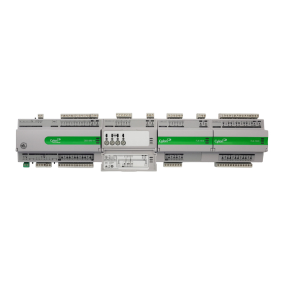
CBX System
CBX-8R8|CBX-8R8-H|FLX-4R4|FLX-4R4-H|FLX-8R8|FLX-8R8-H|FLX-16DI
CBX-8R8
8 UniPuts™ + Relays
hardware connections that can be used as
inputs, outputs or relays (software selectable)
8 Universal Inputs
CBX-8R8-H
Including Hand/Off/Auto Local Override
Function
Field Level eXpansion Modules
FLX-4R4
4 UniPuts™ with Relay
4 Universal Inputs
FLX-8R8
8 UniPuts™ with Relay
8 Universal Inputs
FLX-16DI
16 Digital Inputs
FLX-4R4-H, FLX-8R8-H
Including Hand/Off/Auto Local Override
Function
Support for Cylon smart thermostat bus
LED status on all I/O channels provides
indication of fault or override status
Compact form factor to maximize enclosure
space
Scalable from 16 points to 64 points using FLX
modules
Easy module expansion using simple bus
connectors
Up to 64 Trendlogs, 1024 entries per Trendlog
Accurate Universal Inputs support a variety of
thermistors and RTDs that range from 0 to 450 kΩ
WWW.CYLON.COM
WWW.CYLON-AUTOMATRIX.COM
INSTALLATION GUIDE : see page 5
page 1 of 14
Advertisement
Table of Contents

Related Manuals for Cylon FLX-8R8


Summary of Contents for Cylon FLX-8R8
- Page 1 Function protocol communications simultaneously including BACnet® MS/TP and Modbus® RTU. Support for Cylon smart thermostat bus The fully programmable CBX-8R8(-H) can be tailored to meet a LED status on all I/O channels provides variety of applications by creating and modifying strategies using...
-
Page 2: Specifications
15 m / 50 ft. using 22 AWG conductors FLX bus Connection FLX bus connector carries inter-module communications and module power WWW.CYLON.COM DS0119 rev 40 ©2018 Cylon All Rights Reserved. Subject to change without notice page 2 of 14 WWW.CYLON-AUTOMATRIX.COM... -
Page 3: Cbx-8R8 And Cbx-8R8-H
REPLACE ONLY WITH THE SAME OR EQUIVALENT TYPE RECOMMENDED BY THE MANUFACTURER. DISPOSE OF USED BATTERIES ACCORDING TO THE MANUFACTURER'S INSTRUCTIONS. WWW.CYLON.COM DS0119 rev 40 ©2018 Cylon All Rights Reserved. Subject to change without notice page 3 of 14 WWW.CYLON-AUTOMATRIX.COM... -
Page 4: System Architecture
SYSTEM ARCHITECTURE WWW.CYLON.COM DS0119 rev 40 ©2018 Cylon All Rights Reserved. Subject to change without notice page 4 of 14 WWW.CYLON-AUTOMATRIX.COM... - Page 5 The Modbus Terminator Switch is located beside the port. If the switch is towards the icon, then termination is in and if the switch is towards the icon then termination is out. WWW.CYLON.COM DS0119 rev 40 ©2018 Cylon All Rights Reserved. Subject to change without notice page 5 of 14 WWW.CYLON-AUTOMATRIX.COM...
- Page 6 Note: During typical operation, the Red LED should be on, the Green LED should be blinking, and the Yellow LED should be off. WWW.CYLON.COM DS0119 rev 40 ©2018 Cylon All Rights Reserved. Subject to change without notice page 6 of 14...
-
Page 7: Installation
ON at end at one end of network network only switch set to OFF network daisy-chained to next device of network only WWW.CYLON.COM DS0119 rev 40 ©2018 Cylon All Rights Reserved. Subject to change without notice page 7 of 14 WWW.CYLON-AUTOMATRIX.COM... -
Page 8: Bacnet® Communications
CBX. If you are using Windows 8.1 this driver may not be available by default, please contact Cylon TSG for a copy of the driver. Once connected to the controller, it is possible to change the settings on the... - Page 9 Slide one RMC connector into the T-slot of the CBX or FLX at the point at which the BUS is to be extended. WWW.CYLON.COM DS0119 rev 40 ©2018 Cylon All Rights Reserved. Subject to change without notice page 9 of 14...
-
Page 10: Add The Controller To The Site
I/O Modules 5.3. Set up the CBX and connected FLX in a Site Configuration Utility Comms Controller to In the Cylon (CCConfig) select the which the device is connected, and add a new controller by clicking the button: When FLX modules have been added, the specific FLX type can be set in the... - Page 11 Strategy drawing has been set up, the blocks associated with that FLX’s IO will be ‘greyed out’ to indicate that they are inactive. WWW.CYLON.COM DS0119 rev 40 ©2018 Cylon All Rights Reserved. Subject to change without notice page 11 of 14...
-
Page 12: Operation
109 … 116 FLX address 1 FLX address 2 201 … 208 209 … 216 301 … 308 309 …316 FLX address 3 WWW.CYLON.COM DS0119 rev 40 ©2018 Cylon All Rights Reserved. Subject to change without notice page 12 of 14 WWW.CYLON-AUTOMATRIX.COM... -
Page 13: Auxiliary Power Outputs
In this mode the output toggles between the voltages defined as “ON” and “OFF”. Note: If UCU Room Display is used, refer to the DS0064 UCU10FC/K for the corresponding Strategy Point Setup. WWW.CYLON.COM DS0119 rev 40 ©2018 Cylon All Rights Reserved. Subject to change without notice page 13 of 14 WWW.CYLON-AUTOMATRIX.COM... -
Page 14: Output Override
This allows the strategy to react to the fact that a point has been overridden. Note: The corresponding terminal LED will indicate the override condition. WWW.CYLON.COM DS0119 rev 40 ©2018 Cylon All Rights Reserved. Subject to change without notice page 14 of 14 WWW.CYLON-AUTOMATRIX.COM...
Need help?
Do you have a question about the FLX-8R8 and is the answer not in the manual?
Questions and answers