
Related Manuals for SilverStone BS50


Summary of Contents for SilverStone BS50
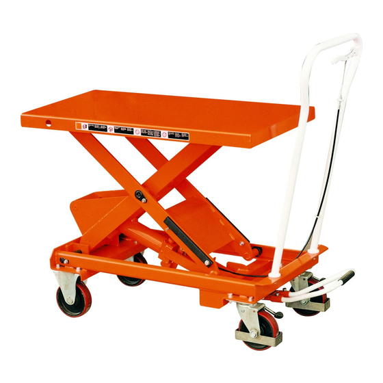
- Page 1 Instruction Manual BS Series NOTE: Owner/Operator must read and understand this instruction manual before using the lift table. RevB: 02/2009...
-
Page 2: Scissors 1
Operation and Service Manual BEFORE OPERATING THE LIFT TABLE, READ THIS MANUAL CAREFULLY AND UNDERSTAND COMPLETELY. KEEP THIS MANUAL ON FILE FOR FUTURE REFERENCE. IF THIS IS LOST, PLEASE CONTACT YOUR LOCAL SUPPLIER FOR A NEW COPY. ALSO, IF THE WARNING/CAUTION DECAL ON THE UNIT IS LOST, PLEASE CONTACT YOUR LOCAL SUPPLIER FOR A NEW DECAL. - Page 3 Press the lifting pedal several times the until the table reaches the desired position. The table does not elevate after reaching the highest position even if the lifting pedal is pressed. The table lowers slightly after reaching the highest position. MAXIMUM CAPACITY OF TABLE BS15 BS25 BS50 BS75...
-
Page 4: Link Pin .
5. Specifications Wheel Capacity Table Table L×W×H Pedal to top. Weight Model Stroke (mm) (kg) (mm) Height(mm) (mm) (approx. times) (kg) φ BS15 700×450 225-760 1000×450×950 BS25 830×500 335-915 1100×500×1010 BS50 1010×520 430-1000 1130×520×1185 BS75 1010×520 432-1000 1130×520×1260 BS100 1000 1010×520... - Page 5 7. Hydraulic Circuit...
-
Page 7: Table Of Contents
DESCRIPTION DESCRIPTION Table pair Spring washer Guide roller Washer Scissors Bushing Snap ring Steel ball Link pin Steel ball holder Safety pin Relief spring Hex bolt Regulating pressure plug Washer O ring Frame pair Relief plug Front wheel O ring Spring washer Plug Hex. - Page 8 O ring Valve rodⅠ Steering bush Control link O ring Roll pin Discharge lever Roll pin Valve arm Check ring Socket head screw Cylinder Assembly 13-21 Pump Unit Assembly 64-78 Pump Unit Sub Assembly 22-58 Handle Assembly 84-91 Pedal Assembly 76-77 Seal kit ass'y 14,15,20,23,29,31,32,40,42,44,55,57,74...
- Page 10 DESCRIPTION DESCRIPTION Seal cover d30×D42×7 Lever bushing Cylinder cover Washer 6 O-ring d63×2.65 Spring washer 6 O-ring d30×3.55 Hex soch screw M6×16 Piston rod Put pressure assembly line Spacing casing Nut M8 Guide ringδ1.5×15 Washer 8 O-ring D20×2.4 Spring pin Seal ring d34×D40×4.5 Control link Piston rod retainer...
-
Page 11: Front Wheel 2
Y-ring 100. Washer 10 Pump body for plunger 101. Satety rod O-ring d28×3.1 102. Screw bolt M10×40 Pump body 103. Spring pin 8×30 O-ring d10.6×2.65 104. Roller for table Spring 105. Table Reflux rod 106. Pin axle O-ring d4×1.8 107. Pin axle Guide casing 108. -
Page 13: Piston Rod
DESCRIPTION DESCRIPTION Seal cover d30×D42×7 Hex soch screw M6×16 Cylinder cover Put pressure assembly line O-ring d63×2.65 Washer 8 O-ring d30×3.55 Spring pin 5×14 Piston Rod Control link Spacing casing Handle Guidering δ1.5×15 Spacing casing O-ring D20×2.4 Spring washer 12 Seal ring d34×D40×4.5 Hex screw M12×30 10. -
Page 14: Spring
42. O-ring D28×3.1 101. Internal scissors lever 43. Pump body 102. Pin axle for chassis 44. O-ring d10.6×2.65 103. Spring washer 8 45. Spring 104. Hex screw M8×16 46. Reflux rod 105. Pin axle for scissons 47. O-ring d4×1.8 106. Pin axle for table 48. -
Page 16: Conical Valve 1
DESCRIPTION DESCRIPTION Seal cover d35×D43.5×5 Put pressure assembly line Cylinder cover Washer 8 O-ring d75×3.55 Spring pin O-ring d35.5×3.55 Control link Piston Rod Handle Spacing casing Spacing casing Guideing δ2×15 Spring washer 12 O-ring D20×2.4 Hex screw M12×30 Seal ring d39×D45×4.5 Split pin 2×15 10. -
Page 17: Plunger 1
42. Pump body for plunger 103. Oil cup 43. O-ring D28×3.1 104. Bolt M8×12 44. Pump body 105. Internal scissors lever 45. O-ring d10.6×2.65 106. Chassis 46. Spring 107. axle 47. Reflux rod 108. Hex soch screw M10×25 48. O-ring d4×1.8 109. -
Page 19: Washer
DESCRIPTION DESCRIPTION Seal cover d35×D43.5×5 Put pressure assembly line Cylinder cover Washer 8 O-ring d75×3.55 Spring pin O-ring d35.5×3.55 Control link Piston Rod Handle Spacing casing Spacing casing Guideing δ2×15 Spring washer 12 O-ring D20×2.4 Hex screw M12×30 Seal ring d39×D45×4.5 Split pin 2×15 10. -
Page 20: O-Ring
41. Y-ring d10×D18×6 102. Bushing 42. Pump body for plunger 103. Oil cup 43. O-ring D28×3.1 104. Bolt M8×12 44. Pump body 105. Internal scissors lever 45. O-ring d10.6×2.65 106. Chassis 46. Spring 107. axle 47. Reflux rod 108. Hex soch screw M10×25 48. -
Page 22: Bushing
DESCRIPTION DESCRIPTION Seal cover d30×D42×7 Put pressure assembly line Cylinder cover Washer 8 O-ring d63×2.65 Spring pin O-ring d30×3.55 Control link Piston Rod Handle Spacing casing Spacing casing Guideing δ1.5×15 Spring washer 12 O-ring D20×2.4 Hex screw M12×30 Seal ring d34×D40×4.5 Split pin 2×15 10. - Page 23 42. O-ring D28×3.1 102. Table 43. Pump body 103. Spring pin 8×30 44. O-ring d10.6×2.65 104. Screw bolt M10×40 45. Spring 105. Safety rod 46. Reflux rod 106. Nut M10 External scissors lever 47. O-ring d4×1.8 107. chassis Internal scissors lever 48.
-
Page 25: Seal Ring
DESCRIPTION DESCRIPTION Seal cover d35×D43.5×5 Spring pin Cylinder cover Control link O-ring d75×3.55 Handle 3A O-ring d75×2.65 Spacing casing O-ring d35.5×3.55 Spring washer 12 Piston Rod Hex screw M12×30 Spacing casing Split pin 2×15 Guideing δ2×15 O-ring D20×2.4 Pedal bent pipe Seal ring d39×D45×4.5 Hex soch screw M8×20 10. - Page 26 41. Pump body for plunger 102. Table 42. O-ring D28×3.1 103. Spring pin 8×30 43. Pump body 104. Screw bolt M10×40 44. O-ring d10.6×2.65 105. Safety rod 45. Spring 106. Nut M10 46. Reflux rod 107. External scissors lever for chassis 47.
Need help?
Do you have a question about the BS50 and is the answer not in the manual?
Questions and answers